16
Chapter 2: Preparing for Use
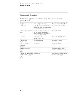
Power Requirements
All power supplies required for operating the logic analyzer are supplied through
the backplane connector in the mainframe.
Operating Environment
The operating environment is listed on page 12. Note the non-condensing
humidity limitation. Condensation within the instrument can cause poor
operation or malfunction. Provide protection against internal condensation.
The logic analyzer module will operate at all specifications within the
temperature and humidity range given on page 12. However, reliability is
enhanced when operating the module within the following ranges:
Temperature: +20
°
C to +35
°
C (+68
°
F to +95
°
F)
Humidity: 20% to 80% non-condensing
Storage
Store or ship the logic analyzer in environments within the following limits:
•
Temperature: -40
°
C to +75
°
C (-40
°
F to +167
°
F)
•
Humidity: Up to 90% at 65
°
C (+149
°
F)
•
Altitude: Up to 15,300 meters (50,000 feet)
Protect the module from temperature extremes which cause condensation on the
instrument.
To inspect the module
1
Inspect the shipping container for damage.
If the shipping container or cushioning material is damaged, keep them until you
have checked the contents of the shipment and checked the instrument
mechanically and electrically.
2
Check the supplied accessories.
One or more of the accessories listed on page 10 are required to operate the
16910/11A logic analyzer module.
3
Inspect the product for physical damage.
Check the module and the supplied accessories for obvious physical or
Summary of Contents for 16900 Series
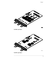
Page 3: ...3 Chapter The 16910A Logic Analyzer The 16911A Logic Analyzer...
Page 8: ...8 Contents...
Page 14: ...14 Chapter 1 General Information...
Page 18: ...18 Chapter 2 Preparing for Use...
Page 61: ...61 4 Calibrating This chapter gives you instructions for calibrating the logic analyzer...
Page 65: ...65 Chapter 5 Troubleshooting Troubleshooting Flowchart 1...
Page 66: ...66 Chapter 5 Troubleshooting Troubleshooting Flowchart 2...
Page 82: ...82 Chapter 5 Troubleshooting To test the cables 18 Return to the troubleshooting flow chart...
Page 94: ...94 Chapter 7 Replaceable Parts 16910A Exploded View Exploded view of the 16910A logic analyzer...
Page 95: ...95 Chapter 7 Replaceable Parts 16911A Exploded View Exploded view of the 16911A logic analyzer...
Page 96: ...96 Chapter 7 Replaceable Parts...
Page 102: ...102 Index...


