84
Chapter 6: Replacing Assemblies
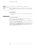
CAUTION:
Turn off the mainframe before installing, removing, or replacing a module.
CAUTION:
Electrostatic discharge can damage electronic components. Use grounded wrist-straps,
mats, and standard ESD precautions when you perform any service to the mainframe or
the modules in it.
Tools Required
•
A T10 TORX screwdriver is required to remove screws that hold the probe cables to
the back panel.
To remove the module
Instructions for removing or installing the module into the mainframe can be
found in the installation guide for the mainframe.
If you don’t have the installation guide for your mainframe, you can find the latest
version on the Internet at www.agilent.com.
For example: to find the installation guide for a 16900A-series mainframe, go to
www.agilent.com and enter
16900A installation guide
in the quick search box. Then
scroll down to
Manuals, Guides & Notifications
to find the
16900A-Series Logic
Analysis Systems Installation Guide
.
Summary of Contents for 16900 Series
Page 3: ...3 Chapter The 16910A Logic Analyzer The 16911A Logic Analyzer...
Page 8: ...8 Contents...
Page 14: ...14 Chapter 1 General Information...
Page 18: ...18 Chapter 2 Preparing for Use...
Page 61: ...61 4 Calibrating This chapter gives you instructions for calibrating the logic analyzer...
Page 65: ...65 Chapter 5 Troubleshooting Troubleshooting Flowchart 1...
Page 66: ...66 Chapter 5 Troubleshooting Troubleshooting Flowchart 2...
Page 82: ...82 Chapter 5 Troubleshooting To test the cables 18 Return to the troubleshooting flow chart...
Page 94: ...94 Chapter 7 Replaceable Parts 16910A Exploded View Exploded view of the 16910A logic analyzer...
Page 95: ...95 Chapter 7 Replaceable Parts 16911A Exploded View Exploded view of the 16911A logic analyzer...
Page 96: ...96 Chapter 7 Replaceable Parts...
Page 102: ...102 Index...


