85
Chapter 6: Replacing Assemblies
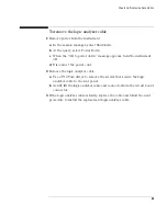
To remove the logic analyzer cable
1
Remove power from the instrument
a
In the session manager, select Shutdown.
b
At the query, select Power Down.
c
When the “OK to power down” message appears, turn the instrument
off.
d
Disconnect the power cord.
2
Remove the logic analyzer cable.
a
Use a T10 Torx driver to remove the screws that secure the logic
analyzer cable to the rear panel.
b
Gently lift the logic analyzer cable end connector from the circuit board
connector.
3
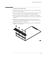
If the logic analyzer cable is faulty, replace the cable and follow the next
procedure to install the replacement logic analyzer cable.
Summary of Contents for 16900 Series
Page 3: ...3 Chapter The 16910A Logic Analyzer The 16911A Logic Analyzer...
Page 8: ...8 Contents...
Page 14: ...14 Chapter 1 General Information...
Page 18: ...18 Chapter 2 Preparing for Use...
Page 61: ...61 4 Calibrating This chapter gives you instructions for calibrating the logic analyzer...
Page 65: ...65 Chapter 5 Troubleshooting Troubleshooting Flowchart 1...
Page 66: ...66 Chapter 5 Troubleshooting Troubleshooting Flowchart 2...
Page 82: ...82 Chapter 5 Troubleshooting To test the cables 18 Return to the troubleshooting flow chart...
Page 94: ...94 Chapter 7 Replaceable Parts 16910A Exploded View Exploded view of the 16910A logic analyzer...
Page 95: ...95 Chapter 7 Replaceable Parts 16911A Exploded View Exploded view of the 16911A logic analyzer...
Page 96: ...96 Chapter 7 Replaceable Parts...
Page 102: ...102 Index...


