41
Chapter 3: Testing Logic Analyzer Performance
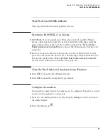
Configure the Logic Analysis System
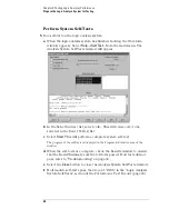
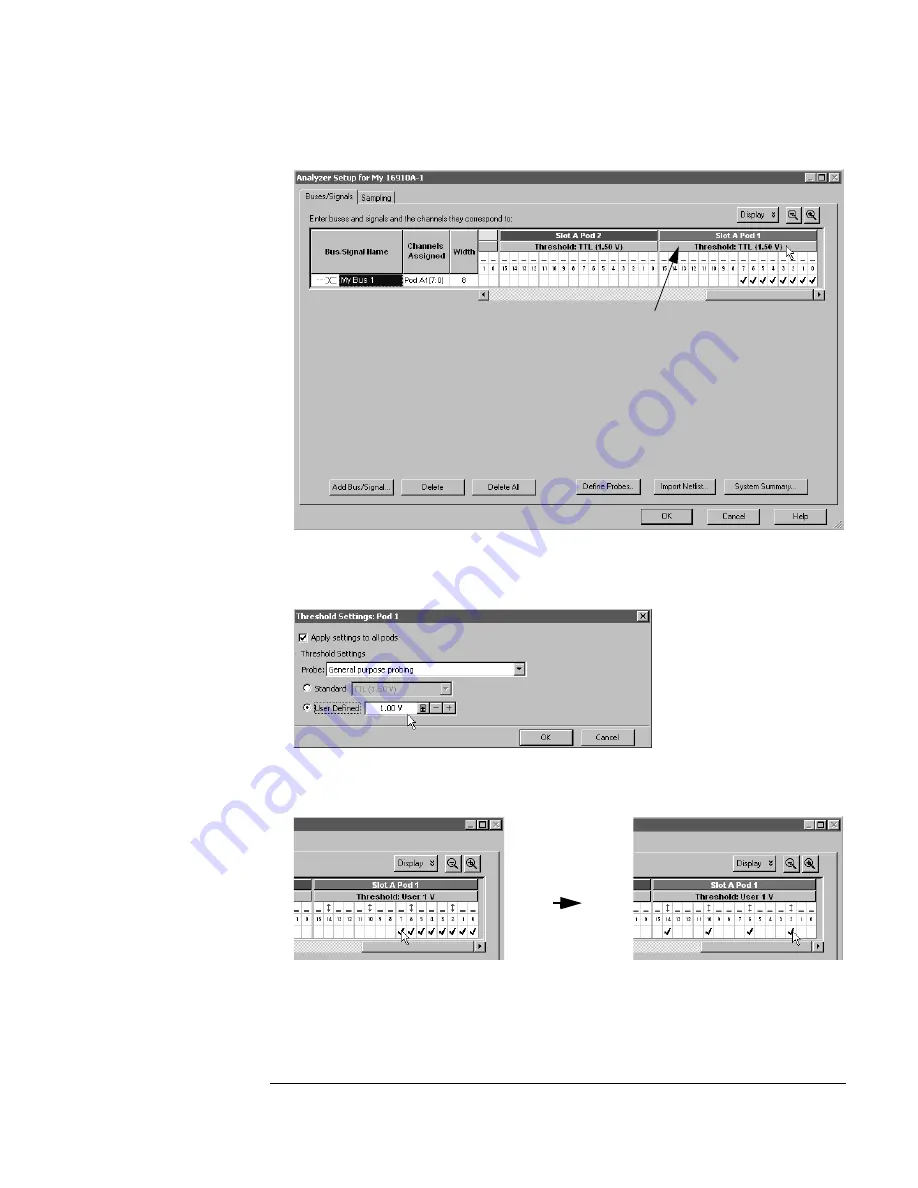
The Threshold Settings window will appear.
c
Set the threshold value for Pod 1 of the 16910/11A logic analyzer to 1 V
and select
OK
.
d
The activity indicators will now show activity on the channels that are
connected to the pulse generator.
e
Un-assign all channels. Hint: you can do this quickly by clicking on the
left-most check mark and dragging to the right across all of the other
check marks. If you have a model 16902A logic analysis system
Click here
Summary of Contents for 16900 Series
Page 3: ...3 Chapter The 16910A Logic Analyzer The 16911A Logic Analyzer...
Page 8: ...8 Contents...
Page 14: ...14 Chapter 1 General Information...
Page 18: ...18 Chapter 2 Preparing for Use...
Page 61: ...61 4 Calibrating This chapter gives you instructions for calibrating the logic analyzer...
Page 65: ...65 Chapter 5 Troubleshooting Troubleshooting Flowchart 1...
Page 66: ...66 Chapter 5 Troubleshooting Troubleshooting Flowchart 2...
Page 82: ...82 Chapter 5 Troubleshooting To test the cables 18 Return to the troubleshooting flow chart...
Page 94: ...94 Chapter 7 Replaceable Parts 16910A Exploded View Exploded view of the 16910A logic analyzer...
Page 95: ...95 Chapter 7 Replaceable Parts 16911A Exploded View Exploded view of the 16911A logic analyzer...
Page 96: ...96 Chapter 7 Replaceable Parts...
Page 102: ...102 Index...

