87
Chapter 6: Replacing Assemblies
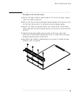
To replace the circuit board
1
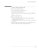
Remove the logic analyzer cables using the “To remove the logic analyzer
cable” procedure on page 85.
2
Remove the four screws attaching the ground spring and back panel to the
circuit board, then remove the back panel and the ground spring.
3
Replace the faulty circuit board with a new circuit board. On the faulty
board, make sure the 2x15 (30-pin) ribbon cable is connected between J15
and J12.
4
Position the ground spring and back panel on the back edge of the
replacement circuit board. Install four screws to connect the back panel
and ground spring to the circuit board.
5
Install the logic analyzer cables using the procedure “To install the logic
analyzer cable” on page 86.
Summary of Contents for 16900 Series
Page 3: ...3 Chapter The 16910A Logic Analyzer The 16911A Logic Analyzer...
Page 8: ...8 Contents...
Page 14: ...14 Chapter 1 General Information...
Page 18: ...18 Chapter 2 Preparing for Use...
Page 61: ...61 4 Calibrating This chapter gives you instructions for calibrating the logic analyzer...
Page 65: ...65 Chapter 5 Troubleshooting Troubleshooting Flowchart 1...
Page 66: ...66 Chapter 5 Troubleshooting Troubleshooting Flowchart 2...
Page 82: ...82 Chapter 5 Troubleshooting To test the cables 18 Return to the troubleshooting flow chart...
Page 94: ...94 Chapter 7 Replaceable Parts 16910A Exploded View Exploded view of the 16910A logic analyzer...
Page 95: ...95 Chapter 7 Replaceable Parts 16911A Exploded View Exploded view of the 16911A logic analyzer...
Page 96: ...96 Chapter 7 Replaceable Parts...
Page 102: ...102 Index...


