Theory of Operation
8
16901A Logic Analysis System Service Guide
91
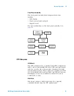
Front Panel Assembly
The front panel assembly block diagram shown here
includes:
•
LCD display.
•
Touch screen board and grid.
•
Keypad board.
For more information on the front panel assembly to to
.
CPU Subsystem
CPU Board
The CPU motherboard is a standard microATX configuration
with 1 GB of system RAM. The exact CPU and speed grade
will vary over the life of the product. Standard I/Os built
into the ATX board are PS/2, serial port, parallel port, USB
2.0, 10/100 Mbit LAN, and VGA Video. One PCI slot and one
PCI Express x1 slot are available for added I/O such as
1 Gbit LAN or video.
Disk Drive
The frame contains a SATA hard drive. It is logically
controlled directly from the CPU motherboard.
Flat Panel
LCD Display
Front Panel
Board
Backlight
Inverter Board
Touch Screen
Board (Option 103)
Touch Screen
Grid (Option 103)
Motherboard
PCI Express x16
Connector
Motherboard
USB Connector
Keypad
Board
MIB Board
Connector
Summary of Contents for 16901A
Page 1: ...Agilent Technologies Agilent 16901A Logic Analysis System Service Guide...
Page 6: ...6 16901A Logic Analysis System Service Guide...
Page 10: ...10 16901A Logic Analysis System Service Guide Contents...
Page 18: ...18 16901A Logic Analysis System Service Guide 2 Preparing for Use...
Page 22: ...22 16901A Logic Analysis System Service Guide 3 Testing Performance...
Page 42: ...42 16901A Logic Analysis System Service Guide 5 Troubleshooting...
Page 102: ...102 16901A Logic Analysis System Service Guide 8 Theory of Operation...

