General Power Meter Functions
2
N1911A/1912A P-Series Power Meters User’s Guide
99
Recorder Output
The rear panel
Recorder Output
connectors (1 and 2) produce a dc
voltage that corresponds to the power level in Watts of the channel
depending on the measurement mode. This dc voltage ranges from 0 to
+1 Vdc. The output impedance is typically 1 k
Ω
. Channel and display
offsets, and duty cycle have no effect on the Recorder Outputs.
For example, the Recorder Outputs can be used to:
• Record swept measurements
• Level an output from a source using external leveling
• Monitor the output power
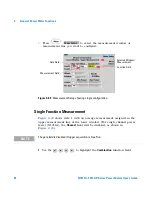
To access the
Recorder
menu press
, and enable Rec o/p. This
allows you to switch the Recorder Output signal either on or off. The
and
softkeys allow you to scale the power levels to
represent the 1 Vdc maximum and 0 Vdc minimum output voltage of the
Recorder Output.
Procedure
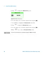
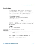
Set the recorder output as follows:
1
Press
,
to display the
Measurement Setup
menus.
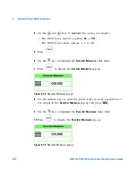
2
Use the
and
keys to highlight the
Rec o/p:
setting field.
3
Press
to reveal the
Recorder
option menu.
Max Power
Min Power
N O T E
Ensure you have selected the channel you want to set up.
Meas Select

