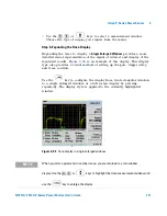
Using E9320 E-Series Power Sensors
4
N1911A/1912A P-Series Power Meters User’s Guide
135
Configuring a Peak Power Measurement
While the P- Series power meter may at first seem complex, configuring a
measurement and displaying the results are quickly achieved using trace
markers or by following a step- by- step process of numeric data entry.
Before configuring the measurements, you should have some information
about the signal you want to measure. The following information for
example, can help you quickly establish stable triggering and reliable
measurement data:
•
the Center Frequency (CF)
•
the bandwidth of any modulating signal
•
the expected maximum and minimum power levels
•
timing information for any pulsed signals
You can configure the required measurements using numeric data entry
from the keypad or remote interface or, by manually positioning trace
markers using the front panel controls.
Setting up the power meter using the trace markers is a more interactive
process and may require more iterations between channel, triggering, gate,
and display functions to make a measurement. However, it is ideally suited
to measuring an unknown signal.
TIP
If pulsed signal timing information is unavailable or incomplete,
you may prefer to use the trace and marker functions to
configure your measurement.
N O T E
You must select continuous or single triggered mode to enable the use of trace markers.

