9
CCDF
224
N1911A/1912A P-Series Power Meters User’s Guide
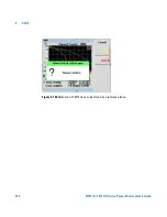
While the marker is moving along the trace, the power (dB) and the
probability (%) will be reflected at the lower left corner as shown in
Figure 9- 151
. Row 1 shows the reading for Marker 1 while row 2 shows
the reading for Marker 2. The lower right corner shows the delta reading
for Marker 2- Marker 1, average measurement, peak measurement and the
peak- to- average ratio for the respective channel that you have selected.
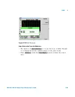
Step 3: Setting the Scale/Div
•
You are allowed to optimize the view of the trace by setting the
appropriate scale/div. The lowest limit is 0.1 dB while the highest limit
is 50 dB. A warning message will appear if the lower or upper limit has
been exceeded.
N O T E
The alphabet in the parenthesis after Average, Peak and Peak-Average measurements
represents: (A) - Channel A, (B) - Channel B, (G) - Gaussian, and (R) - Reference.
N O T E
Press
once to view the displayed trace in full-screen.
N O T E
Marker control menu is also accessible in the
Trace Control
menu.


