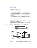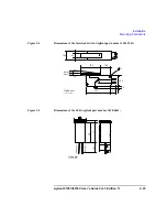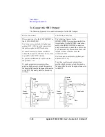
Agilent 4155C/4156C User’s Guide Vol.1, Edition 11
2-33
Installation
Mounting Connectors
To Make an Interlock Circuit
The interlock circuit is designed to prevent electrical shock when a user touches the
measurement terminals.
CAUTION
You must install an interlock circuit on a shielding box to prevent hazardous
voltages when the door of the shielding box is open.
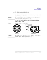
Figure 2-2 shows the pin assignments of the interlock connector mounted on a
connector plate or test fixture.
Figure 2-2
Interlock Connector Pin Assignments
WARNING
Potentially hazardous voltages may be present at the Force, Guard, and Sense
terminals when the interlock terminals are shorted.
Summary of Contents for 41501A
Page 19: ...Contents Agilent 4155C 4156C User s Guide Vol 1 Edition 11 9 Accessories and Options...
Page 20: ...Agilent 4155C 4156C User s Guide Vol 1 Edition 11 Contents...
Page 21: ...1 Introducing the 4155C 4156C...
Page 41: ...2 Installation...
Page 84: ...2 44 Agilent 4155C 4156C User s Guide Vol 1 Edition 11 Installation Maintenance...
Page 85: ...3 Connecting to Network...
Page 129: ...4 File Operations...
Page 152: ...4 24 Agilent 4155C 4156C User s Guide Vol 1 Edition 11 File Operations Backing Up a Diskette...
Page 153: ...5 Print Plot Function...
Page 198: ...5 46 Agilent 4155C 4156C User s Guide Vol 1 Edition 11 Print Plot Function Output Examples...
Page 199: ...6 External Keyboard...
Page 203: ...7 Initial Settings...
Page 209: ...8 Specifications...
Page 243: ...9 Accessories and Options...


