background image

2-26

Agilent 4155C/4156C User’s Guide Vol.1, Edition 11

Installation

Installing Accessories

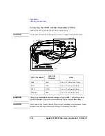
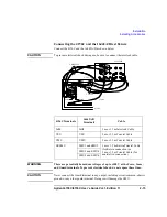
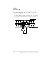
To Connect the 16440A Selector to the 4155C/4156C 

Connecting two 16440A selectors

If you use two 16440A, connect the Control Output terminal of the selector to 
the Control Input terminal of the second selector using a 40 cm control cable as 
shown below.

Summary of Contents for 41501A

Page 1: ...ies Agilent 4155C Semiconductor Parameter Analyzer Agilent 4156C Precision Semiconductor Parameter Analyzer User s Guide Silicon Investigations Repair Information Contact Us 920 955 3693 www siliconin...

Page 2: ...consequential damages in connec tion with the furnishing use or per formance of this document or of any information contained herein Should Agilent and the user have a separate written agreement with...

Page 3: ...61000 4 2 1995 A1 1998 A2 2001 IEC 61000 4 3 2002 A1 2002 EN 61000 4 3 2002 A1 2002 IEC 61000 4 4 2004 EN 61000 4 4 2004 IEC 61000 4 5 2001 EN 61000 4 5 1995 A1 2001 IEC 61000 4 6 2003 EN 61000 4 6 1...

Page 4: ...Category With reference to the equipment types in the WEEE Directive Annex I this product is classed as a Monitoring and Control instrumentation product Do not dispose in domestic household waste To r...

Page 5: ...he instrument chassis and cabinet must be connected to an electrical ground The power terminal and the power cable must meet International Electrotechnical Commission IEC safety standards DO NOT OPERA...

Page 6: ...Service Office for services and repair to ensure that safety features are maintained DANGEROUS PROCEDURE WARNINGS Warnings such as example below precede potentially dangerous procedures throughout th...

Page 7: ...d before operating equipment Frame or chassis terminal A connection to the frame chassis of the equipment which normally includes all exposed metal structures Indicates earth ground terminal Alternati...

Page 8: ...ing box access door is opened Confirm periodically that INTLK function works normally Before touching the connections of the force guard and sense terminals turn the Agilent 4155C 4156C 41501B off and...

Page 9: ...Agilent 4155C 4156C 41501B HPSMU 200 Vdc MPSMU 100 Vdc 3 Agilent 4155C 4156C 41501B Agilent 16442 Agilent 4155C 4156C 41501B INTLK Output Output HIGH VOLTAGE INTLK SMU...

Page 10: ...ouvert Essayer p riodiquement le fonctionnement normal de verrouillage Avant de toucher la partie connexion partir des bornes de force d appareil de protection et de d tection mettre hors tension le...

Page 11: ...a die Verriegelungsfunktion korrekt arbeitet Schalten Sie die Ger te Agilent 4155C 4156C 41501B aus und entladen Sie alle Kapazit ten bevor Sie die Anschl sse Force Guard und Sense ber hren Falls Sie...

Page 12: ...s how to install the 4155C 4156C accessories and peripherals Connecting to Network This chapter describes how to connect the 4155C 4156C to the network File Operations This chapter describes how to st...

Page 13: ...Results Measurement Units and Functions Support Functions Data Variables and Built in Functions Connecting Measurement Devices Setup Screen Reference This manual is a reference of the setup screens o...

Page 14: ...de Book This manual introduces application measurement examples using the 4155C 4156C and the sample application program disk furnished with the 4155C 4156C VXIplug play Driver User s Guide This manua...

Page 15: ...Power Requirements 2 3 Power Cable 2 3 Line Fuse and Line Voltage Selector for the 41501A 2 5 Ventilation Requirements 2 5 Operating Environment 2 6 Storaging Shipping Environment 2 6 Inspection 2 7 T...

Page 16: ...GNDU Output 2 37 To Connect the SMU Output 2 38 To Connect the VSU VMU PGU Outputs 2 40 Connecting Instruments or Peripherals 2 41 To Connect GPIB Instruments or Peripherals 2 41 To Connect Parallel...

Page 17: ...Up Print Server for Windows 2000 3 28 Setting Up Network for Windows NT 3 30 Setting Up Print Server for Windows NT 3 33 Setting Up NFS Server 3 35 4 File Operations Selecting a Mass Storage Device 4...

Page 18: ...lotting Screen Images 5 8 Printing Plotting Setup Data Lists 5 11 Printing Plotting Measurement Data Lists 5 14 Printing Plotting Measurement Data Graphs 5 17 Saving Screen Images 5 21 Saving Setup Da...

Page 19: ...Contents Agilent 4155C 4156C User s Guide Vol 1 Edition 11 9 Accessories and Options...

Page 20: ...Agilent 4155C 4156C User s Guide Vol 1 Edition 11 Contents...

Page 21: ...1 Introducing the 4155C 4156C...

Page 22: ...sweep measurement function for quick sweep measurements executed by rotating the rotary knob on the front panel The 4155C 4156C can perform stress testing That is can force a specified dc voltage or...

Page 23: ...by using remote control commands The 4155C 4156C provides the following command sets so you can select the command set suitable for your application 4155C 4156C SCPI Standard Commands for Programmable...

Page 24: ...der contains pulse generator units PGUs and additional SMUs The 41501A B is attached to and controlled by the 4155C 4156C Test Fixture Agilent 16442A B is the test fixture for the 4155C 4156C You can...

Page 25: ...11 1 5 Introducing the 4155C 4156C Overview SMU PGU Selector Agilent 16440A SMU Pulse Generator Selector contains two switching circuits to connect the DUT to either an SMU or PGU You can attach anot...

Page 26: ...h resolution source monitor units HRSMUs two voltage source units VSUs two voltage monitor units VMUs The 4156C has higher measurement resolution For details about measurement range and resolution ref...

Page 27: ...onal color active matrix LCD 640 dot H by 480 dot V The flat panel display uses an LCD panel More than 99 99 of the pixels in an LCD are active Inactive pixels less than 0 01 do not indicate a defect...

Page 28: ...group You set the result display format auto analysis definitions and so on Graph List key Moves to GRAPH LIST screen group This softkey toggles between GRAPH and LIST screens Stress key Moves to STR...

Page 29: ...state or standby state if standby is enabled for the channel after measurement is finished Measurement data is appended to data of previous measurement Stop key Stops the measurement or stress Standb...

Page 30: ...to enter alphanumeric and special characters Enter key After you enter desired characters into the data entry field press this key The characters are entered at the field pointer location Also you can...

Page 31: ...Agilent 4155C 4156C User s Guide Vol 1 Edition 11 1 11 Introducing the 4155C 4156C Rear View of the 4155C 4156C Rear View of the 4155C 4156C Figure 1 2 Rear View of the 4155C 4156C...

Page 32: ...rcuit Common and Frame ground terminals Normally connect the terminals together by using the shorting bar Agilent part number 5000 4206 For floating measurement remove the shorting bar CAUTION For flo...

Page 33: ...ge of up to the maximum voltage of SMUs may be present at force guard and sense terminals if the interlock terminal is shorted LAN interface RJ45 connector Ethernet IEEE 802 3 10BASE T for a 10M bps C...

Page 34: ...1 14 Agilent 4155C 4156C User s Guide Vol 1 Edition 11 Introducing the 4155C 4156C Front and Rear View of the 41501A B Front and Rear View of the 41501A B Figure 1 3 Front and Rear View of the 41501A...

Page 35: ...voltage and position are LINE input receptacle AC power cable is connected to this receptacle Serial number The 41501A B has its own serial number You need this serial number when using the telephone...

Page 36: ...outer conductor is circuit common Ext Pulse Generator Trig Out terminal Trigger pulses synchronized with PGU pulses are output This trigger is used to synchronize the PGU pulse outputs with external p...

Page 37: ...ucing the 4155C 4156C Front and Rear View of the 41501A B 41501A B 410 41501A B 410 has one HPSMU Figure 1 5 Rear View of 41501A B 410 HPSMU terminals There are two triaxial connectors for Kelvin conn...

Page 38: ...SMU5 PGU output terminals BNC connectors Inner conductor is force and outer conductor is circuit common Ext Pulse Generator Trig Out terminal Trigger pulses synchronized with PGU pulses are output Thi...

Page 39: ...4156C Front and Rear View of the 41501A B 41501A B 420 41501A B 420 has two MPSMUs Figure 1 7 Rear View of 41501A B 420 MPSMU terminals Two MPSMUs are installed and each MPSMU has a triaxial connecto...

Page 40: ...s For SMU5 and SMU6 PGU output terminals BNC connectors Inner conductor is force and outer conductor is circuit common Ext Pulse Generator Trig Out terminal Trigger pulses synchronized with PGU pulses...

Page 41: ...2 Installation...

Page 42: ...u do not use the 16442A B test fixture you must connect the Intlk terminal to a switch that turns off when the shielding box access door is opened Confirm periodically that the interlock function work...

Page 43: ...ordance with international safety standards this instrument is equipped with a three prong power cable When connected to an appropriate ac power outlet this cable grounds the instrument frame The type...

Page 44: ...Plug SR 107 2 D1 250 V 10 A PN 8120 2956 Plug IS 1293 and IS 6538 250 V 10 A PN 8120 4211 Plug JIS C 8303 125 V 12 A PN 8121 0743 Plug Israel SI 32 250 V 10 A PN 8120 5182 Plug IRAM 2073 10A 250 V 10...

Page 45: ...ector setting before applying ac line power to the 41501A The line voltage selector switch is located on the rear panel of the 41501A Ventilation Requirements The 4155C 4156C has one cooling fan and t...

Page 46: ...40 C without using flexible disk drive Humidity 20 to 80 RH with using flexible disk drive 15 to 80 RH without using flexible disk drive non condensing and wet bulb temperature 29 C or below Altitude...

Page 47: ...6C and Accessories Perform the following inspections when the 4155C 4156C and accessories arrive at your site Before unpacking any components inspect all boxes for any signs of damage that might have...

Page 48: ...the 41501A B to the outlet 5 If the 41501A B is installed press the LINE button of the 41501A B before pressing the LINE button of the 4155C 4156C 6 Press the LINE button to turn on the 4155C 4156C Th...

Page 49: ...ing to the line frequency of your site B CH A N NE L S C H A N N E L D E FI N I TI O N 01 J A N1 0 0 7 0 5 P M S C H AN N E L D E F U S E R F C T N U S ER V A R E 5 2 5 0A P R O P N E X T P A G E S W...

Page 50: ...Disconnect all cables from the measurement terminals on the 4155C 4156C rear panel 2 Press System key then CALIB DIAG softkey The SYSTEM SELF CALIBRATION DIAGNOSTICS screen is displayed 3 If you want...

Page 51: ...her with the 41501A B weights about 37 kg 81 8 lb The 4155C 4156C is not anchored to the 41501A B Use caution when handling 1 Place the 41501A B on your workbench 2 Place the 4155C 4156C on top of the...

Page 52: ...ion Requirements on page 2 5 This section describes how to install the 16442A B test fixture install the 16441A R box install the 16440A SMU pulse generator selector connect the 16440A to the 4155C 41...

Page 53: ...efore performing this procedure turn off the 4155C 4156C and 41501A B When you use the 16442A B test fixture without the 16441A R box or the 16440A selector you can stabilize the 16442A B as shown in...

Page 54: ...zardous voltages of up to 100 V at the Force and Guard terminals To prevent electrical shock do not expose these lines CAUTION Never connect the Guard terminal to any output including circuit common f...

Page 55: ...s To prevent electrical shock do not expose these lines CAUTION Never connect the Guard terminal to any output including circuit common chassis ground or any other guard terminal Doing so will damage...

Page 56: ...nd the 16442A B test fixture Connect the 41501A B measurement terminals to the 16442A B input as follows WARNING Use Agilent 16493H GNDU cable to connect the GNDU to a test fixture or a connector plat...

Page 57: ...essories Installing the 16442A B test fixture with other accessories The 16442A B test fixture can be installed with an 16441A R box 16440A selector or both The following figure shows how to attach th...

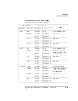
Page 58: ...inals or to the connector plate input terminals using 40 cm triaxial cables as shown below Instrument terminals 16441A Input Cable 4155C MPSMU Input Force 3 m or 1 5 m Triaxial Cable 4156C HRSMU Input...

Page 59: ...g the 16441A R box with other accessories You can attach the 16441A R box to the 16442A B test fixture or to your shielding box as shown in the following figures Attaching the 16441A R Box to the 1644...

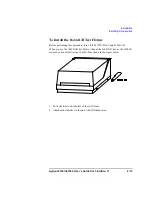
Page 60: ...C 4156C must be equipped with an 41501A B SMU pulse generator expander with two PGUs To attach the 16440A selector to the 16442A B test fixture 1 Place the 16440A selector on your workbench 2 Place th...

Page 61: ...steps apply when using two 16440A SMU pulse generator selectors 5 Place the second 16440A on your workbench Place the 16440A selector and the 16442A B test fixture on top of the second 16440A 6 Positi...

Page 62: ...to the 16442A B test fixture and the 16440A selector To attach the 16440A selector to a shielding box The figure above shows the spacing of the 16440A screw holes You need to prepare four screws and...

Page 63: ...you use two 16440As connect the 16440As before connecting to the shielding box as shown below 1 Place the 16440A on your workbench 2 Place the second 16440A on top of the 16440A 3 Position a plate on...

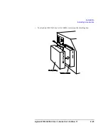
Page 64: ...selector to the shielding box 1 Attach an angle bracket to each side of the 16440A using the screws supplied 2 Place the 16440A s on the side panel of the shielding box 3 Position four nuts on the ins...

Page 65: ...Agilent 4155C 4156C User s Guide Vol 1 Edition 11 2 25 Installation Installing Accessories To attach an 16441A R box to the 16440A selector on the shielding box...

Page 66: ...talling Accessories To Connect the 16440A Selector to the 4155C 4156C Connecting two 16440A selectors If you use two 16440A connect the Control Output terminal of the selector to the Control Input ter...

Page 67: ...A Terminal Cable 41501A B To SMU Pulse Generator Selector Interface CONTROL Input 3 0 m or 1 5 m Control Cable PGU Input PGU a 3 0 m or 1 5 m Coaxial Cable MPSMU or HPSMU Input SMU 3 0 m or 1 5 m Tria...

Page 68: ...or Plate with 8 Triaxial Connectors 16495J 001 has 8 triaxial through connectors female to female 4 BNC through connectors female to female an Intlk connector and a GNDU connector triaxial through fem...

Page 69: ...2 VMU 16495H INPUT 7 to 12 BNC Cable 16495J INPUT 9 to 12 4156C Intlk 16495H J Intlk 16493J Interlock Cable HRSMU 16495H INPUT 1 to 6 Kelvin Triaxial Cable for Kelvin or Triaxial Cable for non Kelvin...

Page 70: ...rminal is open the 4155C 4156C cannot force high voltage more than 40 V When using the 16442A B test fixture connect the interlock connectors together using the 16493J interlock cable If you use the 1...

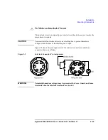
Page 71: ...elvin cable A Kelvin cable requires a Kelvin triaxial connector which has two connector holes and three screw holes 3 Build the interlock circuit shown in To Make an Interlock Circuit on page 2 33 4 A...

Page 72: ...50 0118 BNC Connector female 8150 0447 Wire Connecting PGU to DUT 1250 0118 BNC Connector female 8120 0102 or 8121 1191 Low Noise Coaxial Cable Kelvin Triaxial Connector in mm Triaxial Connector in mm...

Page 73: ...AUTION You must install an interlock circuit on a shielding box to prevent hazardous voltages when the door of the shielding box is open Figure 2 2 shows the pin assignments of the interlock connector...

Page 74: ...s in series between pin number 1 and 2 or 3 of the interlock connector See Figure 2 2 4 Use wire to connect the LED between pin number 4 and 5 or 6 of the interlock connector See Figure 2 2 If the 415...

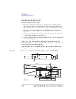
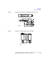
Page 75: ...Figure 2 4 Dimensions of the Interlock Switch Agilent part number 3101 3241 Figure 2 5 Dimensions of the LED Agilent part number 1450 0641 3 1 Switch off Switch on 27 5 10 9 15 9 3 4 27 8 6 8 10 2 4...

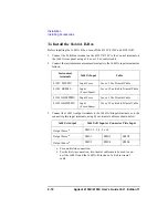
Page 76: ...t 2 Press System key then select CALIB DIAG softkey to display the SYSTEM SELF CALIBRATION DIAGNOSTICS screen 3 In the CALIB DIAG field select DIAG softkey 4 In the CATEGORY field select I O PERIPH so...

Page 77: ...ts of cable resistance connect the Sense line and Force line as close as possible to the terminal of the DUT Short the Sense and Force on the connector as shown below Measurement data will include the...

Page 78: ...pplying high currents extend the guard as far as possible from the front panel connector to the DUT Physically stabilize the cables with tape The following figure is for the HRSMU HPSMU connection usi...

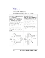
Page 79: ...Never connect the Guard terminal to any output including circuit common chassis ground or any other guard terminal Doing so will damage the SMU WARNING Potentially hazardous voltages up to 100 V 200 V...

Page 80: ...d insulated wire Agilent part number 8150 0447 to connect to a prober socket or DUT Regardless of the output impedance setting use a low noise coaxial cable Agilent part number 8120 0102 from the conn...

Page 81: ...ability connect an GPIB cable between the instrument and the 4155C 4156C If you use an GPIB printer or plotter to make hard copies connect an GPIB cable between the printer or plotter and the 4155C 41...

Page 82: ...command set SCPI or FLEX commands Select 4145 to use the 4145 syntax command set You will also need to set the DELIMITER and EOI fields To Connect Parallel Peripherals The 4155C 4156C has a 25 pin pa...

Page 83: ...eep a good condition It is recommended to perform the calibration once a year at least For the calibration and adjustments contact your nearest Agilent Technologies Service Center Trained service pers...

Page 84: ...2 44 Agilent 4155C 4156C User s Guide Vol 1 Edition 11 Installation Maintenance...

Page 85: ...3 Connecting to Network...

Page 86: ...NFS server and a print server on a network If You Use a HP UX System This section describes information required to use a HP UX system as a server If You Use a Windows PC This section describes examp...

Page 87: ...nto your technical report by using a word processing software You can store files that are too large to store on a diskette This is useful for automatic measurements that store large amounts of data Y...

Page 88: ...h the LAN I F test adapter Agilent part number 04155 61631 furnished with the 4155C 4156C to the LAN connector on the rear panel 3 Press the System key then select the CALIB DIAG softkey to display th...

Page 89: ...ic value from 1 to 32767 System administrator 20 To use remote printer PRINTER c Name of remote printer you use Maximum 15 alphanumeric characters System administrator PRN01 IP ADDRESS IP address of p...

Page 90: ...p 7 Enter the following command using the server to check the network connection of the 4155C 4156C If you use HP UX usr sbin ping 192 168 1 2 If you use Windows C ping 192 168 1 2 This is the example...

Page 91: ...FS server 20 9 PRINTER Share name of a printer registered in the print server PRN01 IP ADDRESS IP address of the print server 192 168 1 1 10 LABEL Softkey label used to specify a directory to mount DA...

Page 92: ...SETUP softkey 2 Select a softkey for the DESTINATION field For the setup shown in Figure 3 2 the PRN01 softkey will be enabled 3 Use the print plot function to do printing If the network printing fai...

Page 93: ...chmod 644 D4156 FILE1 DAT If you use Windows PC To change the permission enter the CACLS command For details of the command enter HELP CACLS to display the help message The following example changes...

Page 94: ...ove the pointer to the FUNCTION field and select the SAVE softkey 4 Move the pointer to the NAME field and enter the file name 5 Move the pointer to the TYPE field and select a softkey to specify the...

Page 95: ...e Figure 3 6 for the example setup Select one of the softkeys in the DESTINATION field to specify a remote printer Do not select the GPIB softkey or PARALLEL softkey that specify a printer connected t...

Page 96: ...dialog box appears 5 Complete the dialog box See Figure 3 5 for the example setup Note that the DESTINATION field must be FILE to save graphics data Specify the data format by selecting one of the so...

Page 97: ...G P I B P A R A L L E L P P R N01 S e l e c t o n e o f t h e s e c o n d a r y s o f t k e y s D E S T I N A T I O N F O R M F E E D D I S A B L E L I N E 6 0 C O L U M N 8 0 C O L O R B W B W P A P...

Page 98: ...on menu Example setup shown in Figure 3 8 defines the file name L IDVG enables output of the unit with data sets the delimiter to comma sets the string mark to double quotation mark and enables output...

Page 99: ...Agilent 4155C 4156C User s Guide Vol 1 Edition 11 3 15 Connecting to Network Using Network Figure 3 9 Reading Spreadsheet Data...

Page 100: ...ing Network Parameters To connect the 4155C 4156C to the network of your site the following network parameters are required These parameters are usually assigned and managed by the network administrat...

Page 101: ...name a maximum 15 alphanumeric characters is available The first character must be a letter of the alphabet To enable NFS server and export a directory to the 4155C 4156C Host name and IP address of...

Page 102: ...ws XP Windows 2000 or Windows NT Hardware Software Required Network Parameters Required Setting Up Network for Windows XP Setting Up Print Server for Windows XP Setting Up Network for Windows 2000 Set...

Page 103: ...Windows XP Professional SP1 with Internet Explorer 6 0 or later or Windows 2000 Professional SP3 with Internet Explorer 6 0 or later For use of Services for UNIX 2 0 Windows 2000 Professional with In...

Page 104: ...only the computer name and the domain name The DHCP server assigns the IP address automatically and changes it dynamically NOTE If you connect the computer to the 4155C 4156C directly and never conne...

Page 105: ...Step 1 Preparation 1 Set up the computer and connect the CD ROM drive to the computer 2 Connect the computer to the network of your site using the straight LAN cable If you are not going to connect th...

Page 106: ...IP is not installed click Install After that step through the setup instruction to install the TCP IP 4 Highlight Internet Protocol TCP IP Step 4 TCP IP Properties 1 Click Properties to open the Inter...

Page 107: ...nts icon to open the Windows Components Wizard 3 In the Components list box highlight Other Network File and Print Services but do not select or clear its check box 4 Click Details to open the Other N...

Page 108: ...s window Step 4 Add Printer If a remote printer is not defined in the computer or you want to add a new printer use the Add Printer Wizard This wizard will guide you in adding a new printer Step throu...

Page 109: ...of the computer Table 3 5 Check List of Network Setup Step 1 Preparation 1 Set up the computer and connect the CD ROM drive to the computer 2 Connect the computer to the network of your site using th...

Page 110: ...ouble click the Network and Dial up Connections icon in the Control Panel 2 Double click the Local Area Connection icon to open the Local Area Connection Status dialog box See Figure 3 10 3 Click Prop...

Page 111: ...OK 4 Click OK 5 Click Close Step 5 Network Connection Check 1 Click Start Programs Accessories and Command Prompt to open the Command Prompt window 2 Ping a computer or a device on the network If for...

Page 112: ...Components to open the Windows Components Wizard See Figure 3 12 3 In the Components list box highlight Other Network File and Print Services but do not select or clear its check box 4 Click Details t...

Page 113: ...new printer Step through the Add Printer Wizard You will not need special instruction Here is how to open the Add Printer Wizard 1 Click Start Settings and Printers to open the Printers folder 2 Doubl...

Page 114: ...net mask optional You can check these values by executing the hostname command and the ipconfig command using the Command Prompt This section describes how to set up the network of the computer Table...

Page 115: ...Windows boots up Step 2 Network Identification 1 Log on to Windows 2 Click Start Settings and Control Panel to open the Control Panel 3 Double click the Network icon to open the Network dialog box 4 C...

Page 116: ...nd set the network parameters 4 Click OK 5 Click OK 6 Restart the computer Step 5 Network Connection Check 1 Log on to Windows 2 Click Start Programs and Command Prompt to open the Command Prompt wind...

Page 117: ...el Step 2 Network Services 1 Double click the Network icon to open the Network dialog box 2 Click the Services tab of the Network dialog box See Figure 3 15 3 If Microsoft TCP IP Printing is not insta...

Page 118: ...in adding a new printer Step through the Add Printer Wizard You will not need special instruction Here is how to open the Add Printer Wizard 1 Click Start Settings and Printers to open the Printers f...

Page 119: ...Perform step 10 to export a network file system Table 3 9 Check List of Setting up NFS Server Steps Summary Step 1 Preparation You add Windows logon accounts and create password file and group file a...

Page 120: ...user01 1234 20 user02 1235 20 3 Create and save a group file for example C test group The file must contain the group name first element group ID third element and group members fourth element separat...

Page 121: ...nstallation is completed you may need to restart the computer Then restart the computer and log on to Windows again NOTE If the computer is going to be a client of a NFS server a software component Cl...

Page 122: ...e component tree of the Services For UNIX Administration window 2 Click Users tab 3 Click New complete the PCNFS Users dialog box and click OK 4 Repeat 3 for all users you want to register 5 Click App...

Page 123: ...X Administration window 2 Click Maps tab 3 Click Show User Maps of the Advanced maps 4 Select Windows domain name for example PC001 for the computer named PC001 5 Click List Windows Users Windows logo...

Page 124: ...nced maps 4 Select Windows domain name for example PC001 for the computer named PC001 5 Click List Windows Groups Windows groups will be listed on the Windows groups list box 6 Click List UNIX Groups...

Page 125: ...ame of backup file 4 Click Back Up to create the backup file The backup file saves the user mapping and group mapping data you set at Step 7 and Step 8 5 Click Apply Finally close the Services for UNI...

Page 126: ...r radio button b Enter Share name for example DATA4156 This value will be set to the 4155C 4156C to specify the network file system to mount It must be a maximum 58 alphanumeric characters c Click Per...

Page 127: ...e the permission of the folder as you wish by entering the CACLS command For details of the command refer to the help message displayed by entering the following statement C HELP CACLS Example C CACLS...

Page 128: ...3 44 Agilent 4155C 4156C User s Guide Vol 1 Edition 11 Connecting to Network If You Use a Windows PC...

Page 129: ...4 File Operations...

Page 130: ...hanging the working directory initializing a diskette backing up a diskette You can use these file operations on the internal memory a diskette in the built in flexible disk drive or on a network file...

Page 131: ...n 3 Complete the NETWORK DRIVE SETUP table on the SYSTEM MISCELLANEOUS screen For information on the SYSTEM MISCELLANEOUS screen see Setup Screen Reference manual NOTE Situations When You Cannot Store...

Page 132: ...e in the built in flexible disk drive Insert a diskette into the built in flexible disk drive drive name If you have set up a drive label in the NETWORK DRIVE SETUP table this label will appear as a s...

Page 133: ...e FILE CATALOG area refer to Setup Screen Reference manual To Display File Comments only for diskette If the built in flexible disk drive is specified as the mass storage device the FILE CATALOG area...

Page 134: ...one of the following To store the data in a new file on a diskette enter a file name that is a maximum of 8 characters for DOS format or a maximum of 6 characters for HP LIF format For HP LIF format d...

Page 135: ...softkey for E5250A setup data CST softkey for customized system data This is not available when storing in internal memory 5 In the COMMENT field you may enter a comment of up to 16 characters When us...

Page 136: ...haracters to store on a DOS diskette To store data in a new file on the network file system enter a file name 36 characters maximum The file name and directory path combined can be 58 characters maxim...

Page 137: ...B softkey to specify a tab as the data delimiter COMMA softkey to specify a comma as the data delimiter 8 In the STRING MARK field select NONE softkey to specify no string marker softkey to specify as...

Page 138: ...is OFF the value is output as a numeric value N numeric value 1 user comment User comment is output as a string with a specified string marker Example setups STRING MARK Bipolar Tr Vce Ic 2 VAR1 outpu...

Page 139: ...T OFF STRING MARK DELIMITER COMMA IB 1E 05 to 5E 05 in 1E 05 step 4 variable names Format NO variable name variable name Type S S S Example setups STRING MARK DELIMITER COMMA NO VCE IC 5 unit Format b...

Page 140: ...E 0 0001 to 1 in LOG step IB 1E 05 to 5E 05 in 1E 05 step NO VCE IC V A 1 0 0001 9 265E 10 2 0 00013 1 0416E 09 3 0 00016 1 527E 09 4 0 0002 8 975E 10 5 0 00025 1 7453E 09 2 Microsoft Excel Output Exa...

Page 141: ...le I2 2E 05 to 0 0001 in 2E 05 step Single Append 1 V3 0 to 1 in 0 5 step Append1 I2 2E 05 to 0 0001 in 2E 05 step Append1 Append 2 V3 0 to 1 in 0 5 step Append2 I2 2E 05 to 0 0001 in 2E 05 step Appen...

Page 142: ...softkey to display the SYSTEM FILER screen c Specify the new mass storage device d Select GET softkey 3 In the NAME field do one of following To load a file from a diskette or a network file system a...

Page 143: ...have an HPSMU two parameters will be changed Voltage Measurement Range 200 V 100 V Current Measurement Range 1 A 100 mA If you try to load an 4156A B setup on the 4155C one parameter will be changed C...

Page 144: ...ter a new name The name may be a maximum of 6 characters for a diskette in HP LIF format Do not use _ as the last character of the filename a maximum of 8 characters for a diskette in DOS format To st...

Page 145: ...y 7 Press SELECT softkey This sets the NAME and TYPE entries 8 Select EXECUTE softkey then select one of the following YES softkey to remove the file directory NO softkey to cancel 9 Select EXIT softk...

Page 146: ...copy from a diskette or a network file system a Select FILE CATALOG softkey b Move the pointer to the desired file name using the rotary knob c Press SELECT SOURCE softkey This sets the SOURCE NAME an...

Page 147: ...mum To copy a file to an existing file a Select FILE CATALOG softkey b Move the pointer to the desired file name using the rotary knob c Press SELECT TARGET softkey This sets the TARGET NAME entry To...

Page 148: ...FILER softkey to display the SYSTEM FILER screen 3 Specify the mass storage device as a network file system 4 Select MAKE DIRECTORY softkey 5 In the NAME field enter the new directory name The direct...

Page 149: ...rage device as a network file system 4 Select FILE CATALOG softkey 5 To specify the working directory a Move the pointer to the desired directory using the rotary knob b Select CHANGE DIRECTORY softke...

Page 150: ...tkey to display the setup fields 6 In the DISK OPERATION field select DISK INIT softkey 7 In the FORMAT field select DOS softkey or HP LIF softkey 8 Optional In the VOLUME NAME field enter a volume na...

Page 151: ...select one of the following YES softkey to execute the disk copy NO softkey to cancel the disk copy 8 After the target diskette message is displayed remove the source diskette and insert an initializ...

Page 152: ...4 24 Agilent 4155C 4156C User s Guide Vol 1 Edition 11 File Operations Backing Up a Diskette...

Page 153: ...5 Print Plot Function...

Page 154: ...easurement data from the GRAPH LIST LIST screen Graphs of measurement data from the GRAPH LIST GRAPHICS and KNOB SWEEP screens This chapter explains how to use the print plot function and consists of...

Page 155: ...e HR TIFF High resolution TIFF For saving screen images or measurement graph hard copy images to a TIFF file Output quality is higher than the TIFF mode The display screens and output format available...

Page 156: ...utput resolution quality depends on RESOLUTION setting HP GL Position size and aspect ratio are defined by OUTPUT REGION Print speed is faster than PCL Data List Output PCL Print starting point is def...

Page 157: ...ect the output quality To set the output size and position do the following procedure in the PRINT PLOT GRAPH PLOT or SCREEN DUMP dialog box 1 In the RESOLUTION field select one softkey 75 DPI to 600...

Page 158: ...8A Parallel PCL HR PCL B W FIX COLOR e P 75 150 300 HP DeskJet 660C C2164A Parallel PCL HR PCL B W FIX COLOR e P 75 150 300 HP DeskJet 694C Parallel PCL HR PCL B W FIX P 75 100 150 300 600 f HP DeskJe...

Page 159: ...P 90 150 HP ThinkJet 2225A C D GPIB Parallel PCL B W P 75 HP PaintJet 3630A GPIB PCL B W FIX COLOR P HP 7440A 7475A plotters GPIB HP GL B W FIX L HP 7550B plotter GPIB HP GL B W FIX L a Available par...

Page 160: ...lds properly For more information see Setup Screen Reference manual SYSTEM PRINT PLOT SETUP screen This screen specifies the printer plotter information to print plot paper size and so on Set all the...

Page 161: ...vailable PRINT PLOT Executes the screen dump PR PL SETUP Displays the PRINT PLOT SETUP screen To close the PRINT PLOT SETUP screen select EXIT softkey EXIT Closes the SCREEN DUMP dialog box and quits...

Page 162: ...one of the softkeys or enter a value using the keyboard or the ENTRY keys on the front panel The following softkeys are available for each OUTPUT REGION field WHOLE Sets the output region as the enti...

Page 163: ...all the entry fields properly For more information see Setup Screen Reference manual SYSTEM PRINT PLOT SETUP screen This screen specifies the printer plotter information to print plot paper size and...

Page 164: ...select EXIT softkey EXIT Closes the PRINT PLOT SETUP DATA dialog box and quits the print plot function 2 To set the DESTINATION to PRINTER PLOTTER select PRINTER PLOTTER softkey 3 To set the LANGUAGE...

Page 165: ...vailable for each OUTPUT REGION field WHOLE Sets the output region as the entire sheet UPPER LEFT Sets the output region to the upper left quarter of the paper UPPER RIGHT Sets the output region to th...

Page 166: ...all the entry fields properly For more information see Setup Screen Reference manual SYSTEM PRINT PLOT SETUP screen This screen specifies the printer plotter information to print plot paper size and...

Page 167: ...EXIT softkey EXIT Closes the PRINT PLOT DATA LIST dialog box and quits the print plot function 2 To set the DESTINATION to the PRINTER PLOTTER select PRINTER PLOTTER softkey 3 To set the LANGUAGE sele...

Page 168: ...ch OUTPUT REGION field WHOLE Sets the output region as the entire sheet UPPER LEFT Sets the output region to the upper left quarter of the paper UPPER RIGHT Sets the output region to the upper right q...

Page 169: ...all the entry fields properly For more information see Setup Screen Reference manual SYSTEM PRINT PLOT SETUP screen This screen specifies the printer plotter information to print plot paper size and s...

Page 170: ...ER PLOTTER UPPER LEFT X 5 Y 0 PRINT PLOT COMMENT LANGUAGE PCL RESOLUTION 75 DPI LOWER RIGHT X 100 Y 100 PRINT SETUP DATA YES GRAPH PLOT OUTPUT REGION DESTINATION PRINTER PLOTTER UPPER LEFT X 5 Y 0 PRI...

Page 171: ...ct the HR PCL mode setting the resolution too low will result in poor print quality 4 If you select HR PCL or HP GL set the GRAPH TRACE ONLY field by selecting YES or NO softkey YES Graph trace only o...

Page 172: ...ower left quarter of the paper LOWER RIGHT Sets the output region to the lower right quarter of the paper STORE REGION Stores the OUTPUT REGION settings in the internal memory RECALL REGION Recalls th...

Page 173: ...ets the DISK entry field to specify the mass storage device used to save a PCL HP GL or TIFF file See Setup Screen Reference manual SYSTEM PRINT PLOT SETUP screen This screen specifies the information...

Page 174: ...EXIT Closes the SCREEN DUMP dialog box and quits the print plot function 2 To set the DESTINATION to FILE select FILE softkey 3 Enter the file name in the FILE NAME field To save a file to a diskette...

Page 175: ...e following softkeys or enter a value using the keyboard or the ENTRY keys on the front panel These softkeys are available for each OUTPUT REGION field WHOLE Sets the output region as the entire sheet...

Page 176: ...ing SYSTEM FILER screen This screen sets the DISK entry field to specify the mass storage device used to save a PCL or HP GL file For more information see Setup Screen Reference manual SYSTEM PRINT PL...

Page 177: ...file save PR PL SETUP Displays the PRINT PLOT SETUP screen To close the PRINT PLOT SETUP screen select EXIT softkey EXIT Closes the PRINT PLOT SETUP DATA dialog box and quits the print plot function 2...

Page 178: ...softkeys CURRENT Selects the currently displayed setup screen GROUP Selects the screen group that includes the currently displayed setup data ALL Selects all the setup screens 6 If you select HP GL se...

Page 179: ...ut region to the upper half of the paper the OUTPUT REGION should be defined as follows OUTPUT REGION UPPER LEFT X 0 Y 0 origin of printer LOWER RIGHT X 100 Y 50 7 Optional Enter a comment of up to 58...

Page 180: ...a list check the following SYSTEM FILER screen This screen sets the DISK entry field to specify the mass storage device used to save a PCL or HP GL file See Setup Screen Reference manual SYSTEM PRINT...

Page 181: ...le save PR PL SETUP Displays the PRINT PLOT SETUP screen To close the PRINT PLOT SETUP screen select EXIT softkey EXIT Closes the PRINT PLOT DATA LIST dialog box and quits the print plot function 2 To...

Page 182: ...ved a Select the data INDEX numbers 1 to 100 by entering the following OUTPUT DATA INDEX NO 1 100 b Select all the measurement data by selecting ALL softkey 6 If you select HP GL set the OUTPUT REGION...

Page 183: ...ut region to the upper half of the paper the OUTPUT REGION should be defined as follows OUTPUT REGION UPPER LEFT X 0 Y 0 origin of printer LOWER RIGHT X 100 Y 50 7 Optional Enter a comment of up to 58...

Page 184: ...the following SYSTEM FILER screen This screen sets the DISK entry field to specify the mass storage device used to save a PCL HP GL or TIFF file See Setup Screen Reference manual SYSTEM PRINT PLOT SE...

Page 185: ...EFT X 5 Y 0 PRINT PLOT COMMENT LANGUAGE PCL RESOLUTION 75 DPI LOWER RIGHT X 100 Y 100 PRINT SETUP DATA YES FILE NAME GRAPH PLOT OUTPUT REGION DESTINATION FILE UPPER LEFT X 5 Y 0 PRINT PLOT COMMENT GRA...

Page 186: ...OS format a maximum of 6 characters for HP LIF format Do not use _ as the last character of the filename To save a file to the network drive the file name can be a maximum of 36 characters The file na...

Page 187: ...set the OUTPUT REGION There are two available fields UPPER LEFT Specifies the position of the upper left corner of the printed or plotted hard copy LOWER RIGHT Specifies the position of the lower righ...

Page 188: ...be defined as follows OUTPUT REGION UPPER LEFT X 0 Y 0 origin of printer LOWER RIGHT X 100 Y 50 8 Optional Enter a comment of up to 58 characters in the PRINT PLOT COMMENT field This comment is print...

Page 189: ...Edition 11 5 37 Print Plot Function Output Examples Output Examples This section shows examples of the 4155C 4156C print plot output Screen Dump Output Setup Data List Output Measurement Result List...

Page 190: ...erJet printer in landscape mode Setup Screen GRAPH LIST GRAPHICS USER COMMENT on the Screen ID VG CHARACTERISTICS SYSTEM PRINT PLOT SETUP screen FORM FEED ENABLE COLOR B W B W PAPER SIZE A4 FEED DIR L...

Page 191: ...Agilent 4155C 4156C User s Guide Vol 1 Edition 11 5 39 Print Plot Function Output Examples Output Example...

Page 192: ...LS CHANNEL DEFINITION USER COMMENT on the Screen ID VG CHARACTERISTICS SYSTEM PRINT PLOT SETUP screen FORM FEED ENABLE COLOR B W B W LINE 60 PAPER SIZE A4 FEED DIR SHORT SIDE OUTPUT ITEM ENABLE for al...

Page 193: ...SETUP DATA Jan 10 20 00 00 2001 PAGE 1 ID VG CHARACTERISTICS SAMPLE DEVICE1 CHANNELS CHANNEL DEFINITION MEASUREMENT MODE SWEEP CHANNELS MEASURE STBY SERIES UNIT VNAME INAME MODE FCTN RESISTANCE SMU1...

Page 194: ...een GRAPH LIST LIST USER COMMENT on the Screen ID VG CHARACTERISTICS SYSTEM PRINT PLOT SETUP screen FORM FEED ENABLE COLOR B W B W LINE 60 PAPER SIZE A4 FEED DIR SHORT SIDE OUTPUT ITEM ENABLE for all...

Page 195: ...in 50mV step VSB 0 0000 V to 2 0000 V in 500 0mV step NO VG ID V A 1 1 000 V 10 89pA 2 950mV 11 01pA 49 1 400 V 2 44708mA Second sheet Agilent 4156C DATA LIST Jan 10 20 00 00 2001 PAGE 2 ID VG CHARAC...

Page 196: ...APHICS USER COMMENT on the Screen ID VG CHARACTERISTICS SYSTEM PRINT PLOT SETUP screen FORM FEED ENABLE COLOR B W B W LINE 60 COLUMN 80 PAPER SIZE A4 FEED DIR SHORT SIDE OUTPUT ITEM ENABLE for all INI...

Page 197: ...pends on the printer Agilent 4156C GRAPH PLOT Jan 10 20 00 00 2001 PAGE 1 ID VG CHARACTERISTICS SAMPLE DEVICE 1 V S 0 0 0 0 0 0 0 0 0 0 0 V A V G 1 0 0 0 V 1 0 0 m I D d e c a d e d i v 1 0 0 p 1 0 0...

Page 198: ...5 46 Agilent 4155C 4156C User s Guide Vol 1 Edition 11 Print Plot Function Output Examples...

Page 199: ...6 External Keyboard...

Page 200: ...erview in Chapter 1 For correspondence when using the Instrument BASIC refer to Programmer s Guide NOTE The following functions are not available for the external keyboard Keys not on the external key...

Page 201: ...t F7 MEASUREMENT key group Single Ctrl S Repeat Ctrl R Append Ctrl A Stop Ctrl C Standby Ctrl Y Stress Ctrl T green key Single Ctrl N green key Stop Ctrl Z Integ Time key group Short Ctrl I Medium Ctr...

Page 202: ...rl Shift R Edit key group Ctrl B Shift Tab or Backspace green key Ctrl Shift B Ctrl Shift Tab or Ctrl Backspace Ctrl F or Tab green key Ctrl Shift F or Ctrl Tab Delete Delete or Alt D Insert Insert or...

Page 203: ...7 Initial Settings...

Page 204: ...after applying power and set the 4155C 4156C according to the files This function saves you the trouble of getting application files every time you turn on the 4155C 4156C default initial settings If...

Page 205: ...amming file If an IBASIC programming file with name AUTOST is on the diskette this file is automatically loaded and started after loading the files for setting setup and result screens and internal me...

Page 206: ...by RENAME or COPY When you create INIT MES or INIT DAT file by using RENAME or COPY function on the SYSTEM FILER screen you cannot select which screen is displayed The CHANNELS CHANNEL DEFINITION scr...

Page 207: ...e as follows Measurement Units Measurement units that are verified as operating normally are turned on and set to the idle state Setup items of setup and result screens These items are set to the defa...

Page 208: ...istor Vce Ic characteristics measurement setup data for FET field effect transistor Vds Id characteristics measurement setup data for FET field effect transistor Vgs Id characteristics measurement set...

Page 209: ...8 Specifications...

Page 210: ...orm arithmetic calculations Display measured and calculated results on the LCD display Perform graphical analysis Store and recall measurement setups and measurement and graphical display data Dump to...

Page 211: ...ents The measurement and output accuracies are specified at the rear panel connector terminals when referenced to the Zero Check terminal under the following conditions 1 23 C 5 C double for 5 to 18 C...

Page 212: ...tage or current to prevent damaging the device under test Voltage 0 V to 100 V Current 100 fA to 100 mA Compliance accuracy Same as current voltage set accuracy HRSMU supplemental information Allowabl...

Page 213: ...idity See Table 8 2 1 fA 4 20 fA 1 fA Vout 100 c d 100 V 100 pA 10 fA 4 400 fA c d 1 fA 4 40 fA 10 fA Vout 100 c d 100 V 1 nA 100 fA 0 5 0 7 pA 1 fA Vout 10 fA 0 5 0 4 pA 1 fA Vout 100 V 10 nA 1 pA 0...

Page 214: ...18 to 28 C 1 2 28 to 40 C 2 5 Voltage Range Set Reso Set Accuracy a a Accuracy of reading or setting value offset value Meas Reso Measurement Accuracy a Max Current b b Vout is the output voltage in v...

Page 215: ...ard offset voltage maximum 1 mV Noise characteristics typical filter ON Voltage source 0 01 of V range rms Current source 0 1 of I range rms Voltage monitor 0 02 of V range p p Current monitor 0 2 of...

Page 216: ...supplemental information Output resistance typical 0 2 Capacitive load maximum 10 F Slew rate maximum 0 2 V s Current limit typical 120 mA Output Noise typical 1 mV rms Voltage Range Resolution Accur...

Page 217: ...0 01 of range p p when the integration time is 10 PLC Differential mode measurement noise typical 0 005 of range p p when the integration time is short Voltage Range Meas Reso Meas Accuracy a a Accur...

Page 218: ...ent Compliance Limiting The SMU can limit output voltage or current to prevent damaging the device under test Voltage 0 V to 100 V Current 1 pA to 100 mA Compliance accuracy Same as current voltage se...

Page 219: ...fA Vout 100 V 10 nA 1 pA 0 5 7 pA 20 fA Vout 10 fA 0 5 5 pA 20 fA Vout 100 V 100 nA 10 pA 0 12 50 pA 200 fA Vout 100 fA 0 1 30 pA 200 fA Vout 100 V 1 A 100 pA 0 12 400 pA 2 pA Vout 1 pA 0 1 200 pA 2...

Page 220: ...ccuracy of reading or setting value offset value Iout is the output current in amps Meas Reso Measurement Accuracy a Max Current b b Vout is the output voltage in volts 2 V 100 V 0 03 900 V 0 3 Iout 2...

Page 221: ...nt damaging the device under test Voltage 0 V to 200 V Current 1 pA to 1 A Compliance accuracy Same as current voltage set accuracy HPSMU supplemental information Allowable cable resistance Kelvin con...

Page 222: ...20 fA Vout 200 V 100 nA 10 pA 0 12 50 pA 200 fA Vout 100 fA 0 1 30 pA 200 fA Vout 200 V 1 A 100 pA 0 12 400 pA 2 pA Vout 1 pA 0 1 200 pA 2 pA Vout 200 V 10 A 1 nA 0 12 5 nA 20 pA Vout 10 pA 0 1 3 nA...

Page 223: ...al connection Single triaxial connector Kelvin remote sensing Supplemental information Load capacitance 1 F Cable resistance Force 1 Sense 10 Voltage Range Set Reso Set Accuracy a a Accuracy of readin...

Page 224: ...535 Trigger output Level TTL Timing same timing and width as PGU1 pulse output Pulse dc Output Voltage and Accuracy See Table 8 8 Timing Parameters See Table 8 9 Accuracy of Timing parameters The foll...

Page 225: ...0 2 100 ps Slew rate maximum 100 V s 50 output impedance to 50 load Noise 0 2 of range at dc output Table 8 8 Pulse dc Output Voltage and Accuracy Set Parameter Voltage Range Resolu tion Accuracy a a...

Page 226: ...s 1 s to 999 s 0 to 1000 s 1 s 3 1 ms to 10 ms 0 01 ms to 9 99 ms 0 to 10 ms 10 s 4 10 ms to 100 ms 0 1 ms to 99 9 ms 0 to 100 ms 100 s 5 100 ms to 1000 ms 1 ms to 999 ms 0 to 1000 ms 1 ms 6 1 s to 1...

Page 227: ...6C User s Guide Vol 1 Edition 11 8 19 Specifications Functions Functions Measurement setup Measurement capability Arithmetic and analysis functions Repeating and automating test Output Data storage Ot...

Page 228: ...me domain measurements are available Voltage Current Sweep Measurement Characteristics SMUs or VSUs can be set using VAR1 primary sweep VAR2 subordinate sweep VAR1 synchronous sweep or CONST constant...

Page 229: ...ed offset value CONSTANT A source unit can be set as a constant voltage or current source depending on the unit PULSE One of SMUs can be set as a pulse source Pulse width 0 5 ms to 100 ms 100 s resolu...

Page 230: ...at thinned out mode to 1 s range 80 s resolution 1 s to 65 535 s range 2 ms resolution Hold time initial wait time 0 03 to 655 35 s 100 s resolution Stop condition a condition to stop the sampling ca...

Page 231: ...he current measurement and voltage measurement and the stray capacitance and leakage current of measurement path etc refer to supplemental data shown below Zero Offset Cancels stray capacitance of the...

Page 232: ...egration Time Maximum Value Meas Reso Accuracy 10 pA 100 pA 0 5 sec 100 fF 1 pF 5 fF 4 2 70 pF 1 sec 2 pF 20 pF 10 fF 4 3 90 pF 2 sec 76 pF 760 pF 20 fF 4 3 130 fF 1 nA 0 1 sec 700 pF 10 fF 0 84 160 f...

Page 233: ...ess Knob Sweep In the knob sweep mode sweep range is controlled instantaneously with the front panel rotary knob Only the CHANNELS CHANNEL DEFINITION screen needs to be defined Standby Mode Measuremen...

Page 234: ...eraging COND conditional evaluation Physical constants Keyboard constants are stored in memory as follows q Electron Charge 1 602177 E 19 C k Boltzmann s Constant 1 380658 E 23 e Dielectric Constant o...

Page 235: ...matically determined using automatic analysis user function and read out functions User Variable Displays the data on the screen via GPIB or Instrument BASIC Repeating and Automating Test Instrument C...

Page 236: ...te control Instrument BASIC is remote controllable from an external computer via the GPIB interface IBASIC supplemental information Program text area 16 Kbyte Variable stack area 500 Kbyte Common vari...

Page 237: ...t V More than 99 99 of the pixels on an LCD are active Hard Copy Functions Graphics hard copy measured data and all data appearing on the screen can be output via GPIB parallel or network interface to...

Page 238: ...gram are compatible Network mass storage device Mass storage device an NFS mountable mass storage device File types auto start program file initial setup file measurement setup file measurement setup...

Page 239: ...L4 SR1 RL1 PP0 DC1 DT1 C1 C2 C3 C4 C11 E2 Parallel interface RJ45 connector Ethernet IEEE 802 3 10BASE T for a 10Mbps CSMA CD local area network External keyboard compatible PC style 101 key keyboard...

Page 240: ...User s Guide Vol 1 Edition 11 Specifications Functions Sample Application Programs Flash EEPROM test TDDB Constant I Electromigration test V Ramp test J Ramp test SWEAT GO NO GO test HCI degradation...

Page 241: ...emperature 29 C or below without disk drive operation Storage 5 to 90 RH non condensing and wet bulb temperature 39 C or below Altitude Operating 0 to 2 000 m Storage 0 to 4 600 m Power requirement 90...

Page 242: ...hed accessories for the 4155C 4156C Triaxial Cable 4 ea 4155C Kelvin Triaxial Cable 4 ea 4156C Coaxial Cable 4 ea Interlock Cable 1 ea Keyboard 1 ea User Manual 1 set Sample Application Program Disk 1...

Page 243: ...9 Accessories and Options...

Page 244: ...terlock 4 coaxial 4 triaxial cables 4155C A6J ANSI Z540 compliant calibration 4155C UK6 Commercial cal certificate w test data 4155C 0KN Self paced Training Kit 4156C Precision Semiconductor Parameter...

Page 245: ...4156C 16442A 011 Add 3 0 m triaxial cables for 4156C 16442A 800 Extra blank teflon board 16442A 801 Universal socket module 0 1 inch pitch with 10 pins 16442A 802 Universal socket module 0 075 inch pi...

Page 246: ...n 16493K 001 1 5 m length 16493K 002 3 0 m length 16495H Connector plate w 6 triax 6 coax intlk GNDU 16495H 001 Bulkhead feedthrough connectors female to female 16495H 002 Connectors to contacts for s...

Reviews: