2-40
Agilent 4155C/4156C User’s Guide Vol.1, Edition 11
Installation
Mounting Connectors
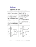
To Connect the VSU/VMU/PGU Outputs
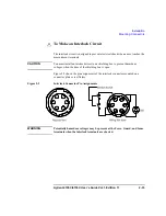
The following figures show connection examples for VSU/VMU and PGU output.
VSU/VMU connector
PGU connector
Use AWG 24 single-strand insulated wire
(Agilent part number 8150-0447) to connect
to a prober, socket, or DUT.
Regardless of the output impedance setting,
use a low-noise coaxial cable (Agilent part
number 8120-0102) from the connector to a
prober, socket, or DUT.
If you use an 16440A selector, use a
low-noise coaxial cable (Agilent part number
8121-1191).
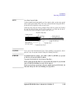
Common
Signal line
Insulator
Plate
Wire
BNC
connector
to
DUT
Common
Signal line
Insulator
Plate
Coaxial cable
BNC
connector
to
DUT
Summary of Contents for 41501A
Page 19: ...Contents Agilent 4155C 4156C User s Guide Vol 1 Edition 11 9 Accessories and Options...
Page 20: ...Agilent 4155C 4156C User s Guide Vol 1 Edition 11 Contents...
Page 21: ...1 Introducing the 4155C 4156C...
Page 41: ...2 Installation...
Page 84: ...2 44 Agilent 4155C 4156C User s Guide Vol 1 Edition 11 Installation Maintenance...
Page 85: ...3 Connecting to Network...
Page 129: ...4 File Operations...
Page 152: ...4 24 Agilent 4155C 4156C User s Guide Vol 1 Edition 11 File Operations Backing Up a Diskette...
Page 153: ...5 Print Plot Function...
Page 198: ...5 46 Agilent 4155C 4156C User s Guide Vol 1 Edition 11 Print Plot Function Output Examples...
Page 199: ...6 External Keyboard...
Page 203: ...7 Initial Settings...
Page 209: ...8 Specifications...
Page 243: ...9 Accessories and Options...

