4-26
Agilent 4155B/4156B VXIplug&play Driver User’s Guide, Edition 4
Sample Application Programs for HP VEE
Using sample2.vee
7. Move the wafer to align the probes over the probe plan alignment position, then
click OK in the ALIGN PROBES dialog box.
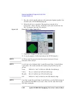
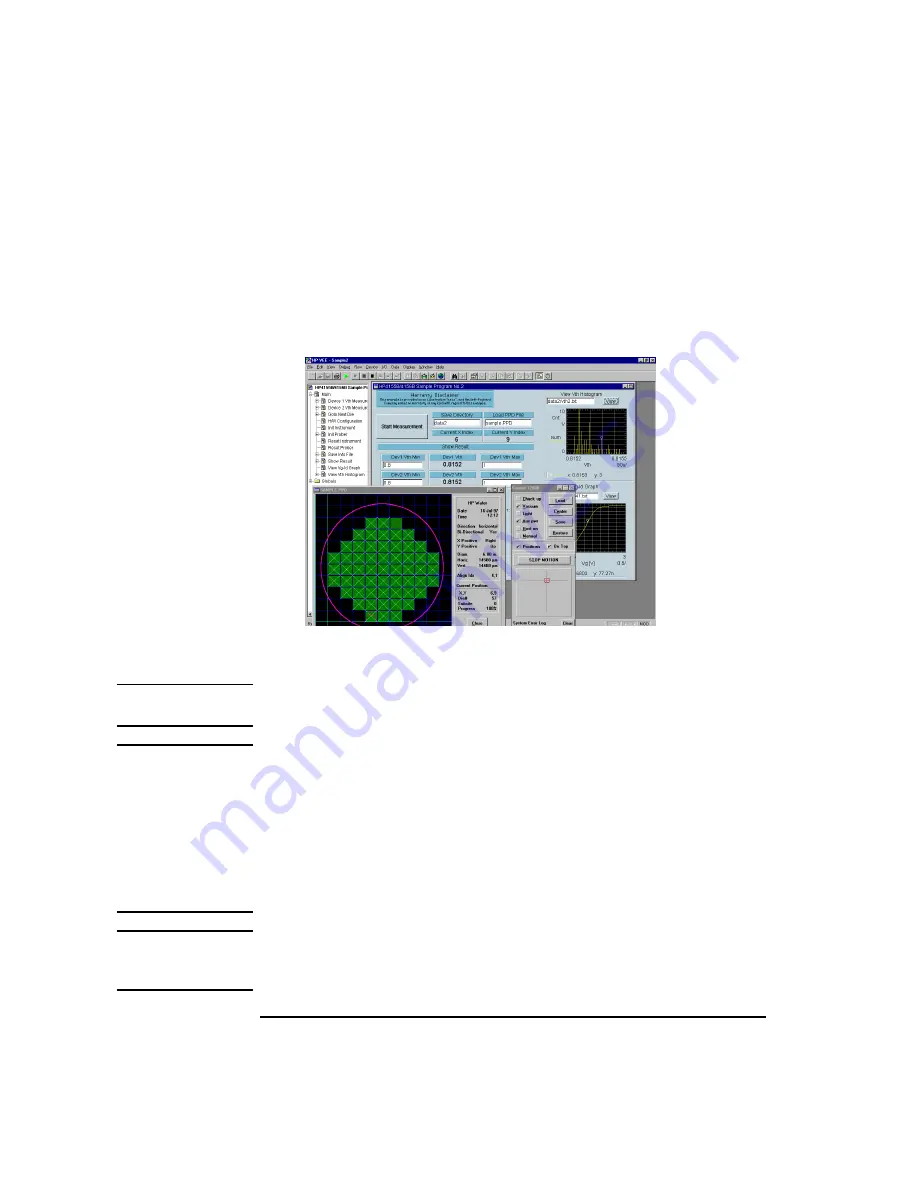
8. Wait until wafer test is completed. The program executes the Id-Vg
measurement, extracts Vth value, displays the results, and stores the data into
files. The program then waits for your input.
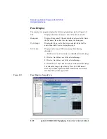
Figure 4-14
Execution Example of sample2.vee
9. Repeat step 2 through 8 for all wafers to be tested.
10. To stop the program, click the stop button on the HP VEE menu bar.
NOTE
In Offline mode, the program returns the dummy data instead of the raw
measurement data in step 8.
NOTE
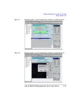
A wafer map is also displayed in the Cascade Microtech Prober Control Software
*.ppd window. The window indicates the results by using the following color
scheme.
Green:
Both device 1 and 2 test data are within the allowable range.
Yellow:
Device 1 test data is out of the allowable range.
Magenta:
Device 2 test data is out of the allowable range.
Red:
Both device 1 and 2 test data are out of the allowable range.
NOTE
To exit the Cascade Microtech Prober Control Software, select the File-Exit menu of
the Cascade Microtech DDE Server window. Then click Yes in the Halt Cascade
DDE Server dialog box.

