Agilent 4155B/4156B VXIplug&play Driver User’s Guide, Edition 4
4-7
Sample Application Programs for HP VEE
Introduction
Measurement Connection and Source Setup
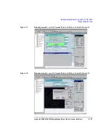
Figure 4-2 shows the measurement connection for instruments, the prober and
devices. This setup is for the fully automatic Online mode. For other modes, ignore
the equipment not used. This figure also shows the default source setup.
Figure 4-2
Measurement Connection and Source Setup
NOTE
To avoid misconnection, pay close attention to the die (device1 and device2) and the
pin assignment of the probe card, if used.
NOTE
In Figure 4-2, OUT 1 to 9 indicates output port 1 to 9 of the matrix card installed in
slot 1 of the E5250A; OUT 23 indicates output port 11 of the card installed in slot 2
of the E5250A.
A
1
9
4
S
SUB
SUB
1
4
3
2
OUT
IN
SMU1
SMU2
SMU3
SMU4
4155/4156
E5250A
Cascade Summit series
semi-auto prober
0.5V
0.5V
to
3.0V
Device1
Device2
0V
0V
3
2
7
5
23
D
G
S
D
G


