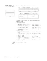
b.
Enter
the
desired
dc
bias
current
value
.
c.
Press
N
NNNNNNNNNNNNNNNNNNNNNNNNNNNNNNNNNNNNNNNNNNNNNN
BIAS
VOLT
LIMIT
.
d.
Enter
the
desired
voltage
limit
value
.
3.
Press
NNNNNNNNNNNNNNNNNNNN
RETURN
.
4.
T
oggle
NNNNNNNNNNNNNNNNNNNNNNNNNNNNNNNNNNNNNNNNNNNN
DC
BIAS
on
OFF
to
NNNNNNNNNNNNNNNNNNNNNNNNNNNNNNNNNNNNNNNNNNNN
DC
BIAS
ON
off
.
5.
V
erify
that
the
DC
BIAS
ON
message
is
displayed.
If
the
voltage
or
the
current
reaches
the
limit
value
,
the
analyzer
limits
the
source
output.
In
that
case
,
the
\# V "
or
\# I "
notation
is
displayed
on
the
left
of
the
screen.
Note
The
dc
bias
must
be
set
after
compensation.
This
is
necessary
because
the
dc
bias
is
automatically
turned
o
when
performing
calibration
or
compensation.
Monitoring
the
OSC
Level
or
the
Dc
Bias
Level
The
level
monitor
function
allows
you
to
monitor
the
voltage
across
the
DUT
or
the
current
through
the
DUT
.
1.
Select
the
channel
on
which
you
want
to
monitor
the
source
level
by
pressing
4
Chan
1
5
or
4
Chan
2
5 .
2.
Press
4
Utilit
y
5 .
3.
Press
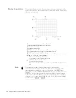
NNNNNNNNNNNNNNNNNNNNNNNNNNNNNNNNNNNNNNNNNNNNNNN
LEVEL
MON
[OFF]
.
4.
Select
the
parameter
that
you
want
to
monitor
.
NNNNNNNNNNNNNN
AC-V
NNNNNNNNNNNNNN
AC-I
NNNNNNNNNNNNNN
DC-V
(Option
001
only)
NNNNNNNNNNNNNN
DC-I
(Option
001
only)
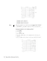
5.
Move
the
marker
to
your
required
stimulus
position.
6.
The
level
at
the
marker
is
displayed
on
the
right
of
the
display
.
Features
Common
to
All
Modes
6-7
Summary of Contents for 4291B
Page 20: ......
Page 24: ...Figure 2 1 Contents 2 4 Installation and Set Up Guide ...
Page 26: ...Figure 2 2 Agilent Part Numbers of Power Cables 2 6 Installation and Set Up Guide ...
Page 34: ...Figure 2 7 Connecting a Keyboard 2 14 Installation and Set Up Guide ...
Page 60: ......
Page 104: ......
Page 130: ......
Page 152: ......
Page 158: ......


