background image

Executing

a

Limit

Line

T

est

1.

Press

4

System

5

N

NNNNNNNNNNNNNNNNNNNNNNNNNNNNNNN

LIMIT

MENU

.

2.

T

oggle

NNNNNNNNNNNNNNNNNNNNNNNNNNNNNNNNNNNNNNNNNNNNNNNNNNNNN

LIMIT

TEST

on

OFF

to

NNNNNNNNNNNNNNNNNNNN

ON

off

.

When

limit

testing

is

turned

on,

an

out-of-limit

test

result

is

indicated

in

ve

ways:

With

a

F

AIL

message

on

the

screen.

With

a

beep

(on/o

selectable).

With

an

asterisk

in

tabular

listings

of

data

(under

4

Copy

5 ).

With

bits

3

and

4

of

the

instrument

status

register

in

the

status

register

.

With

the

GPIB

commands

:DATA?

LFA ,:DATA?

LLIS ,:DATA?

LMAR .

P

erforming

a

List

Sweep

Measurement

The

list

sweep

function

allows

you

to

sweep

the

frequency

according

to

a

predened

sweep

segment

list.

Each

sweep

segment

is

independent

and

can

have

a

dierent

number

of

sweep

points

,

OSC

level,

and

point

averaging.

The

list

sweep

is

used

to

reduce

the

sweep

time

by

setting

coarse

sweep

points

for

the

at

portion

of

wave

form

and

ne

sweep

points

for

the

sharply

curved

portion

of

the

wave

form.

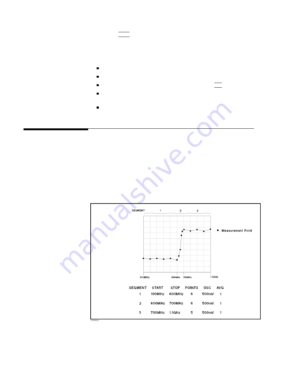
Editing

a

Sweep

List

This

procedure

edits

a

list

sweep

table

to

match

the

example

that

is

shown

in

Figure

6-6.

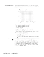
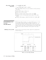
Figure

6-6.

List

Sweep

Example

6-10

Features

Common

to

All

Modes

Summary of Contents for 4291B

Page 1: ... This manual applies directly to instruments with serial number pre x JP1KE and above or whose rmware is version 1 xx For additional important information about serial numbers read Serial Number in Appendix A of this manual Agilent Part No 04291 90031 Printed in JAPAN March 2001 ...

Page 2: ... photocopied reproduced or translated to another language without the prior written consent of the Agilent Technologies Agilent Technologies Japan Ltd Component Test PGU Kobe 1 3 2 Murotani Nishi ku Kobe shi Hyogo 651 2241 Japan MS DOS R is a U S registered trademark of Microsoft Corporation APC 7 R is a U S registered trademark of Bunker Ramo Corporation c Copyright 1997 1998 1999 2001 Agilent Te...

Page 3: ...strument The Agilent Technologies assumes no liability for the customer s failure to comply with these requirements Note 4291B comply with INSTALLATION CATEGORY II and POLLUTION DEGREE 2 in IEC1010 1 4291B are INDOOR USE product Note LEDs in 4291B are Class 1 in accordance with IEC825 1 CLASS 1 LED PRODUCT Ground The Instrument To avoid electric shock hazard the instrument chassis and cabinet must...

Page 4: ...ymbols General de nitions of safety symbols used on equipment or in manuals are listed below Instruction manual symbol the product is marked with this symbol when it is necessary for the user to refer to the instruction manual Alternating current Direct current On Supply O Supply In position of push button switch Out position of push button switch Frame or chassis terminal A connection to the fram...

Page 5: ...A xed to product containing static sensitive devices use anti static handling procedures to prevent electrostatic discharge damage to component v ...

Page 6: ...ies when a name or a variable must be typed in place of the words in italics For example copy lename means to type the word copy to type a space and then to type the name of a le such as file1 Computer Computer font is used for on screen prompts and messages 4HARDKEYS5 Labeled keys on the instrument front panel are enclosed in 4 5 NNNNNNNNNNNNNNNNNNNNNNNNNN SOFTKEYS Softkeys located to the right o...

Page 7: ...ce facility designated by Agilent Technologies Buyer shall prepay shipping charges to Agilent Technologies and Agilent Technologies shall pay shipping charges to return the product to Buyer However Buyer shall pay all shipping charges duties and taxes for products returned to Agilent Technologies from another country Agilent Technologies warrants that its software and rmware designated by Agilent ...

Page 8: ...incidental or consequential damages whether based on contract tort or any other legal theory Assistance Product maintenance agreements and other customer assistance agreements are available for Agilent Technologies products For any assistance contact your nearest Agilent Technologies Sales and Service O ce Addresses are provided at the back of this manual viii ...

Page 9: ... 10 Mounting the Handle and Rack 2 10 Connecting the Test Station 2 11 Connecting the Test Head 2 12 Selecting the Test Head 2 12 Connecting the Test Head to the Test Station 2 12 Connecting a BNC Adapter Option 1D5 Only 2 13 Connecting a Keyboard 2 13 3 Impedance Measurement Quick Start Overview 3 1 Basic Measurement Flow 3 2 Required Equipment 3 3 1 Power ON 3 4 2 Calibration 3 4 Calibration Pro...

Page 10: ...Dielectric Material Measurement Quick Start Overview 4 1 Brief Measurement Theory 4 2 Basic Measurement Flow 4 3 Required Equipment 4 4 1 Power ON 4 5 2 Calibration 4 5 Calibration Procedure 4 6 3 Connecting the Test Fixture 4 9 Connecting the Test Fixture to the Test Head 4 9 Selecting the Test Fixture 4 10 4 Input Load Thickness 4 11 5 Fixture Compensation 4 12 Performing SHORT Compensation 4 12...

Page 11: ...ations 5 18 8 Measuring the MUT 5 19 Performing Automatic Scaling 5 19 9 Analyzing a Measurement Result 5 19 Using the Marker 5 19 Reading a Measured Value 5 19 Moving the Marker to the Maximum Point 5 20 Clearing the Marker 5 21 10 Measuring Other MUTs 5 21 For More Information 5 21 6 Features Common to All Modes Performing User De ned Calibration 6 2 User De ned Calibration Description 6 2 Perfo...

Page 12: ...a Trace to the Memory Trace 6 17 Storing More Traces to Memory Traces 6 17 Displaying Memory Traces 6 18 Displaying a Memory Trace Only When It Is Selected 6 18 Clearing the Memory Traces 6 18 Using the Trace Math Function 6 19 Calculating Using the Data Trace and Memory Trace 6 19 Turning O the Data Math Function 6 19 Saving and Recalling 6 19 Saving an Analyzer Setting and Measurement Trace 6 20...

Page 13: ...n Key Sequence C 6 OPEN Compensation C 7 OPEN Compensation Key Sequence C 7 Connecting DUT C 7 D Fixture Compensation Procedures for the 16194A Exchanging the device holder D 1 Connecting the Test Fixture D 2 Setting D 3 SHORT compensation D 4 Short compensantion key syquence D 4 Open compensation D 5 Open compensation Key syquence D 5 Load compensation D 6 Load compensation Key sequence D 6 DUT D...

Page 14: ... 3 6 3 5 3 7 3 6 3 8 3 6 3 9 3 6 3 10 3 7 3 11 3 7 3 12 3 9 3 13 3 9 3 14 Connecting the Test Fixtures 16192A 3 10 3 15 Fixture Compensation 3 11 4 1 Dielectric Material Measurement 4 2 4 2 Basic Flow for Dielectric Material Measurements 4 3 4 3 Required Equipment 4 4 4 4 Calibration 4 5 4 5 4 6 4 6 4 6 4 7 4 6 4 8 4 7 4 9 4 7 4 10 4 7 4 11 4 8 4 12 4 9 4 13 4 9 4 14 Connecting the Test Fixtures 4...

Page 15: ...mber of Points 6 6 6 4 Level Monitor Function 6 8 6 5 Limit Line Example 6 8 6 6 List Sweep Example 6 10 6 7 Label Function 6 13 6 8 Split Display 6 15 6 9 Uncoupled Channels 6 15 6 10 Marker List 6 16 A 1 Serial Number Plate A 2 D 1 Exchanging the Device Holder D 1 D 2 Connecting the 16194A to the Measurement Terminal D 2 D 3 D 3 D 4 D 4 D 5 Open compensation D 5 D 6 Load compensation D 6 D 7 DUT...

Page 16: ...k Parameter Setting 3 19 3 10 STIMULUS Block Parameter Setting 3 19 4 1 MEASUREMENT Block Parameter Setting 4 17 4 2 STIMULUS Block Parameter Setting 4 17 4 3 MEASUREMENT Block Parameter Setting 4 19 4 4 STIMULUS Block Parameter Setting 4 19 5 1 MUT Size For Test Fixtures 5 9 5 2 MEASUREMENT Block Parameter Setting 5 15 5 3 STIMULUS Block Parameter Setting 5 15 5 4 MEASUREMENT Block Parameter Sett...

Page 17: ...u are rst learning to use the 4291B RF Impedance Material Analyzer Using This Manual The organization of this Quick start Guide is described below Figure 1 1 shows how to use the manual Note that chapters 3 4 and 5 are independent of each other You need only read the chapter that pertains to your measurement or you can read all three Figure 1 1 Manual Reference Flow Chapter 1 Introduction Introduc...

Page 18: ...agnetic Material Measurement Quick Start This chapter provides a quick start guide for magnetic material measurement Magnetic material measurement is available when Option 002 is installed Chapter 6 Features Common to All Modes This chapter provides the procedures for the analyzer key features and measuremnent technique that can be used in all modes of operation impedance dielectric and magnetic A...

Page 19: ...or measuring permeability of ferrite material with Option 002 and 16454A Direct impedance and material parameter measurement versus time humidity or temperature with an external temperature chamber Additional Features Impedance Measurement Evaluate components with dc bias up to 6100 mA and 640 V with Option 001 See Applying Dc Bias Option 001 Only in Chapter 6 Monitor test signals applied to your ...

Page 20: ......

Page 21: ...mple covers panel or display Inspect the shipping container for damage If the shipping container or cushioning material is damaged it should be kept until the contents of the shipment have been checked for completeness and the analyzer has been checked mechanically and electrically The contents of the shipment should be as listed in Table 2 1 If the contents are incomplete if there is mechanical d...

Page 22: ...4291 65006 LOW LOSS Capacitor 04291 60042 Carrying Case3 04291 60041 Sample Program Disk 04291 18000 mini DIN Keyboard C3757 60401 Power Cable See Power Cable Option 012 only Low Impedance Test Head Option 013 only High Temperature High impedance Test Head Temperature Coe cient Measurement Program Disk4 04291 18001 Fixture Stand4 04291 60121 Pad4 04291 09001 1 Delete when Option 011 is ordered 2 D...

Page 23: ...rature Coe cient Measurement Program Disk1 04291 18001 Fixture Stand1 04291 60121 Pad1 04291 09001 Option 0BW only Service Manual2 04291 90111 Option 1D5 only BNC Adapter 1250 1859 1 See the temperature coe cient measurement chapter of Operation Manual 2 This item is not shown in Figure 2 1 Installation and Set Up Guide 2 3 ...

Page 24: ...Figure 2 1 Contents 2 4 Installation and Set Up Guide ...

Page 25: ...en connected to an appropriate ac power outlet this cable grounds the instrument frame The type of power cable shipped with each instrument depends on the country of destination Refer to Figure 2 2 for the part numbers of the power cables available Warning For protection from electrical shock the power cable ground must not be defeated The power plug must be plugged into an outlet that provides a ...

Page 26: ...Figure 2 2 Agilent Part Numbers of Power Cables 2 6 Installation and Set Up Guide ...

Page 27: ...crewdriver to dismount the fuse holder above the AC line receptacle on the rear panel To check or replace the fuse pull the fuse holder and remove the fuse To reinstall the fuse insert a fuse with the proper rating into the fuse holder Caution Use the proper fuse for the line voltage selected Use only fuses with the required current rating and of the speci ed type as replacements DO NOT use a mend...

Page 28: ...tilation make sure that there is adequate clearance of at least 180mm behind and 60mm sides Instruction for Cleaning To prevent electrical shock disconnect the 4291B power cable from the receptacle before cleaning Wipe with a dry cloth or a soft cloth that is soaked with water and wrung tightly without undue pressure to clean the casing Do not attempt to clean the 4291B internally Rack Mounting Ra...

Page 29: ...eft and right front sides of the 4291B 2 Attach the front handles 3 to the sides using the screws provided 3 Attach the trim strips 4 to the handles Option 1CM Rack Mount Kit Option 1CM is a rack mount kit containing a pair of anges and the necessary hardware to mount them to the instrument in an equipment rack with 482 6 mm 19 inches horizontal spacing Mounting the Rack 1 Remove the adhesive back...

Page 30: ...handles attached in an equipment rack with 482 6 mm 19 inches spacing Mounting the Handle and Rack 1 Remove the adhesive backed trim strips 1 from the left and right front sides of the 4291B 2 Attach the front handle 3 and the rack mount ange 5 together on the left and right front sides of the 4291B using the screws provided 3 Remove all four feet lift bar on the inner side of the foot and slide t...

Page 31: ...mainframe is shown in Figure 2 4 While you connect the test station to the mainframe turn o the analyzer Figure 2 4 Connecting the Test Station to the Mainframe 1 Engage the two type N connectors labeled S and R respectively and the center connector 2 Turn the two type N connectors to tighten the connection Installation and Set Up Guide 2 11 ...

Page 32: ... the DUT is less than approximately 10 the low impedance test head provides better measurement accuracy than the high impedance test head For more selection information see the chapter 12 of the Operation Manual Connecting the Test Head to the Test Station How to connect the test head to the test station is shown in Figure 2 5 When you replace the test head turn o the analyzer Figure 2 5 Connectin...

Page 33: ...e analyzer Figure 2 6 Connecting a BNC Adapter Connecting a Keyboard A mini DIN keyboard can be connected to the mini DIN connector on the rear panel of the analyzer The mini DIN keyboard provides an easier way to enter characters for the le names display titles and Instrument BASIC programs It can also access the analyzer softkey functions by using keyboard function keys For more information on t...

Page 34: ...Figure 2 7 Connecting a Keyboard 2 14 Installation and Set Up Guide ...

Page 35: ...he quick start procedures you will have learned how to get the following measurement results 1 Frequency characteristics of impedance 2 Frequency characteristics of capacitance and dissipation factor 3 OSC level characteristics of capacitance and dissipation factor 4 Dc bias voltage characteristics of capacitance and dissipation factor In addition you will also learn how to do the following Use th...

Page 36: ...Basic Measurement Flow Figure 3 1 shows the basic ow for an impedance measurement Figure 3 1 Basic Flow for Impedance Measurements 3 2 Impedance Measurement Quick Start ...

Page 37: ...libration Kit Test Fixture 16191A Side Electrode SMD Test Fixture or 16192A Parallel Electrode SMD Test Fixture or 16193A Small Side Electrode SMD Test Fixture Shorting Device Set Included with 16191A 16192A and 16193A Tweezers Included with 16191A 16192A and 16193A Device Under Test DUT A chip capacitor is demonstrated in this guide Figure 3 2 Required Equipment Impedance Measurement Quick Start ...

Page 38: ...y are installed Other installed option numbers are listed on the rear panel After turning on the analyzer a 30 minute warm up period is required to stabilize the instrument 2 Calibration Calibration de nes the measurement accuracy at the APC 7 R on the test head The calibration must be performed when the analyzer is turned ON After the calibration the analyzer can measure within its speci ed measu...

Page 39: ... that the connector sleeve is extended fully as shown in Figure 3 5 Figure 3 4 Figure 3 5 5 Connect the 0 S termination to the APC 7 R connector as shown in Figure 3 6 Figure 3 6 6 Press NNNNNNNNNNNNNN OPEN After an OPEN calibration sequence of about 1 minute the NNNNNNNNNNNNNN OPEN softkey label is underlined 7 Disconnect the 0 S termination Impedance Measurement Quick Start 3 5 ...

Page 40: ...NNNNNNNNNNNNNN SHORT softkey label is underlined 10 Disconnect the 0 termination 11 Turn only the APC 7 R connector nut of the 50 termination as shown in Figure 3 8 12 Verify that the connector sleeve is retracted fully as shown in Figure 3 9 Figure 3 8 Figure 3 9 13 Connect the 50 termination on the APC 7 R connector as shown in Figure 3 10 3 6 Impedance Measurement Quick Start ...

Page 41: ...you don t need this accuracy for high Q measurements the low loss capacitor calibration can be skipped 16 Connect the low loss capacitor to the APC 7 R connector as shown in Figure 3 11 Figure 3 11 17 Press NNNNNNNNNNNNNNNNNNNNNNNNNNNNNNNNNNNNNNNNNNNNNNNNNNNNNNNN LOW LOSS CAPACITOR After a low loss capacitor calibration sequence of about 1 minute the NNNNNNNNNNNNNNNNNNNNNNNNNNNNNNNNNNNNNNNNNNNNNNN...

Page 42: ...est Fixture Selecting a Test Fixture Agilent Technologies provides the test xtures listed in Table 3 1 for di erent sizes of surface mounted device SMD measurements These xtures provide high stability and repeatability measurements Table 3 1 Test Fixtures Speci cation 1 2 16191A 16192A 16193A DUT Length mm 2 0 to 12 0 1 0 to 20 01 0 5 to 3 2 DUT Width mm 0 5 to 5 0 5 to 5 less than 3 DUT Height mm...

Page 43: ...eps listed below Figure 3 14 shows the connection for 16192A as an example 1 Turn the APC 7 R connector on the test head as shown in Figure 3 12 2 Verify that the connector sleeve is retracted fully as shown in Figure 3 13 Figure 3 12 Figure 3 13 3 Set the mounting posts of the test station into the twin locating holes at the corner of the test xture 4 Connect the connector on the underside of the...

Page 44: ...se the electrical length values for the Agilent Technologies test xtures are stored in the analyzer you can set the electrical length parameter by selecting the xture model number Note You don t have to set an electrical length value when you are going to do load compensation After load compensation you will get save results whether setting electrical length or not Without Option 002 1 Press 4Meas...

Page 45: ...E 5 Select the xture model number that you are using 6 Press NNNNNNNNNNNNNNNNNNNN RETURN NNNNNNNNNNNNNNNNNNNN RETURN 7 Verify that two Del notations appear on the left side of the display 5 Fixture Compensation Fixture compensation reduces the parasitic error existing between the test xture electrode and the test head APC 7 R connector where the measurement accuracy is speci ed Fixture compensatio...

Page 46: ...in Table 3 2 Table 3 2 Dimension of Shorting Devices Dimension mm Agilent Part Number 1 2 1 2 2 4 16191 29001 1 6 2 2 4 2 2 16191 29002 2 4 2 2 4 2 3 2 16191 29003 2 4 2 2 4 2 4 5 16191 29004 0 5 2 0 5 2 1 16191 290051 0 8 2 0 8 2 1 6 16191 290061 0 8 2 1 2 2 2 16191 290071 0 8 2 1 6 2 3 2 16191 290081 1 Extra short devices of Option 010 How to perform SHORT compensation for the 16192A is shown be...

Page 47: ...e so that it contacts the electrode 5 Adjust the two B stages and the two device holders to hold the shorting device 6 Tighten the two B knobs to x the B stages and the device holders 7 1 Push the lever 2 Slide stage A while pushing the lever until the electrode on the stage A slightly contacts the shorting device Impedance Measurement Quick Start 3 13 ...

Page 48: ...rforming OPEN Compensation OPEN Compensation corrects for stray admittance due to the test xture How to perform an OPEN compensation sequence for the 16192A is described as an example The procedures for the 16191A and 16193A are shown in Appendix C 1 Set the DUT on the test xture just as you set the shorting device in the SHORT compensation 2 Push the black lever and remove the DUT OPEN Compensati...

Page 49: ...ompensation 6 Connecting the DUT to the Test Fixture How to connect the DUT to the 16192A is shown in below as an example The procedures for the 16191A and 16193A are shown in Appendix C 1 Push the lever and place the DUT on the electrode 2 Release the lever to hold the DUT 7 Setting up the Analyzer Before you start the measurement you must set up the analyzer to t your measurement requirements Th...

Page 50: ... 4Chan 25 NNNNNNNNNNNNNNNNNNNNNNNNNNNNNNNNNN PHASE z Ch2 Parameter 3 4Format5 4Chan 15 NNNNNNNNNNNNNNNNNNNNNNNNNNNNNNNN LOG Y AXIS Ch1 Format Log 4 4Format5 4Chan 25 NNNNNNNNNNNNNNNNNNNNNNNNNNNNNNNN LIN Y AXIS Ch2 Format Linear STIMULUS Block 5 4Sweep5 NNNNNNNNNNNNNNNNNNNNNNNNNNNNNNNN SWEEP MENU NNNNNNNNNNNNNNNNNNNNNNNNNNNNNNNNNNNNNNNNN SWP SRC FREQ Sweep Frequency 6 4Sweep5 NNNNNNNNNNNNNNNNNNNNNN...

Page 51: ...NN CAPACITNCE PRL Cp Ch1 Parameter Cp 2 4Meas5 4Chan 25 NNNNNNNNNNNNNNNNNNNNNNNNNNNNNNNNNNNNNNNNN D FACTOR D Ch2 Parameter D 3 4Format5 4Chan 15 NNNNNNNNNNNNNNNNNNNNNNNNNNNNNNNN LIN Y AXIS Ch1 Format Linear 4 4Format5 4Chan 25 NNNNNNNNNNNNNNNNNNNNNNNNNNNNNNNN LIN Y AXIS Ch2 Format Linear STIMULUS Block 5 4Sweep5 NNNNNNNNNNNNNNNNNNNNNNNNNNNNNNNN SWEEP MENU NNNNNNNNNNNNNNNNNNNNNNNNNNNNNNNNNNNNNNNNN ...

Page 52: ...NNNNNNNNNNNNNNNNNNN CAPACITNCE PRL Cp Ch1 Parameter Cp 2 4Meas5 4Chan 25 NNNNNNNNNNNNNNNNNNNNNNNNNNNNNNNNNNNNNNNNN D FACTOR D Ch2 Parameter D 3 4Format5 4Chan 15 NNNNNNNNNNNNNNNNNNNNNNNNNNNNNNNN LIN Y AXIS Ch1 Format Linear 4 4Format5 4Chan 25 NNNNNNNNNNNNNNNNNNNNNNNNNNNNNNNN LIN Y AXIS Ch2 Format Linear STIMULUS Block 5 4Sweep5 NNNNNNNNNNNNNNNNNNNNNNNNNNNNNNNN SWEEP MENU NNNNNNNNNNNNNNNNNNNNNNNNN...

Page 53: ...h2 Parameter D 3 4Format5 4Chan 15 NNNNNNNNNNNNNNNNNNNNNNNNNNNNNNNN LIN Y AXIS Ch1 Format Linear 4 4Format5 4Chan 25 NNNNNNNNNNNNNNNNNNNNNNNNNNNNNNNN LIN Y AXIS Ch2 Format Linear STIMULUS Block 5 4Sweep5 NNNNNNNNNNNNNNNNNNNNNNNNNNNNNNNN SWEEP MENU NNNNNNNNNNNNNNNNNNNNNNNNNNNNN DC BIAS V Sweep Dc Bias V 6 4Sweep5 NNNNNNNNNNNNNNNNNNNNNNNNNNNNNNNN SWEEP MENU NNNNNNNNNNNNNNNNNNNNNNNNNNNNNNNNNNNNNNNNN ...

Page 54: ... The value of the bottom of grid is y z REF xx for linear format The scale div value is z The value of the reference position at which the 7 9 locates is xx Note The analyzer has two channels that provide independent measurement and display of the data The traces and grids of the two channels are displayed one over the other The 4Chan 15 and 4Chan 25 keys in the ACTIVE CHANNEL block select which c...

Page 55: ...NNNN SCALE DIV and turm the rotary knob or input scale value as required You will get the measurement results shown on the rst page of this chapter 9 Analyzing a Measurement Result If you can obtain the correct trace on the display you can analyze a measurement result by using the marker and the equivalent circuit analysis function Using the Marker Marker functions allow you to read out the trace ...

Page 56: ...NN MKR COUPLED to NNNNNNNNNNNNNNNNNNNNNNNNNNNNNNNNNNN UNCOUPLED each marker stimulus is controlled independently Moving the Marker to the Minimum Point 1 Press 4Chan 15 2 Press 4Search5 3 Press NNNNNNNNNNNNNNNNNNNNNNNNNNNNNNNNNNN SEARCH MIN 4 The active marker moves to the minimum point on the trace of channel 1 5 Read the marker value displayed on the upper right of the display 3 22 Impedance Mea...

Page 57: ...nstrated Note The equivalent circuit analysis is available when the sweep parameter is frequency Approximation 1 Press 4Display5 2 Press NNNNNNNNNNNNNNNNNNNNNNNNNNNNNNNNNNNNNNNNNNNN EQUIV CKT MENU 3 Press NNNNNNNNNNNNNNNNNNNNNNNNNNNNNNNN SELECT CKT 4 Select NNNNN D for a capacitor Equivalent Circuit Model Selection Model Type Type of DUTs1 A Coils with high core loss B Coils in general Resistors C...

Page 58: ...NNNNNNNNNNNNNNNNNNNNNNNNNNNNN SIMULATE F CHRST 4 The frequency characteristics are simulated and the simulated data is traced on the screen Clearing the Approximated Constant Data 1 Press 4Display5 2 Press NNNNNNNNNNNNNNNNNNNNNNNNNNNNNNNNNNNNNNNNN EQIV CKT MENU 3 Toggle the NNNNNNNNNNNNNNNNNNNNNNNNNNNNNNNNNNNNNNNNNNNNNNNNNNNNNNNN EQIV CKT PARM ON to NNNNNNNNNNNNNNNNN OFF 4 The approximated constan...

Page 59: ...CLEAR MEMORIES 4 The simulated data traces are cleared 10 Measuring Other DUT If you want to measure other DUTs on di erent setups start from 6 Connecting the DUT to the Test Fixture If the next DUT is a di erent size start from 5 Fixture Compensation For More Information Chapter 6 provides procedures for the analyzer s key features and measurement technique for example averaging monitoring level ...

Page 60: ......

Page 61: ... of the quick start procedures you will have learned how to make the following measurements 1 Frequency characteristics of relative permittivity 2 Cole Cole plot The analyzer displays relative permittivity in a complex format The real part r0 represents the energy storage and the imaginary part r00 represents the energy loss term In addition you will also learn how to use the marker Dielectric Mat...

Page 62: ...he relative permittivity from the measured admittance The calculation equation is _ r _ Ym j o d S Where _ r relative permittivity _ Ym measured admittance o permittivity of free space d height of MUT S area of lower electrode Note The above equation is ideal in fact the equation in which the edge e ect and parastic error of test xture is condidered is used For detail refer to Operation Manual 4 2...

Page 63: ...Basic Measurement Flow Figure 4 2 shows the basic ow for a dielectric material measurement Figure 4 2 Basic Flow for Dielectric Material Measurements Dielectric Material Measurement Quick Start 4 3 ...

Page 64: ...tion Kit 16453A Dielectric Material Test Fixture Load Included with 16453A Tweezers Included with 16453A Material Under Test MUT Figure 4 3 Required Equipment Warning The 16454A has the capability for 055 C to 200 C temperature measurement in environmental testing Use globes to prevent scalding when handling heated parts 4 4 Dielectric Material Measurement Quick Start ...

Page 65: ...wer on if they are installed Other installed option numbers are listed on the rear panel After turning on the analyzer a 30 minute warm up period is required to stabilize the instrument 2 Calibration Calibration de nes the measurement accuracy at the APC 7 R on the test head Calibration must be performed when the analyzer is turned ON After calibration the analyzer can measure within its speci ed ...

Page 66: ... the connector sleeve is extended fully as shown in Figure 4 6 Figure 4 5 Figure 4 6 5 Connect the 0 S termination to the APC 7 R connector as shown in Figure 4 7 Figure 4 7 6 Press NNNNNNNNNNNNNN OPEN After an OPEN calibration sequence of about 1 minute the NNNNNNNNNNNNNN OPEN softkey label is underlined 7 Disconnect the 0 S termination 4 6 Dielectric Material Measurement Quick Start ...

Page 67: ...NNNNNNNN SHORT softkey label is underlined 10 Disconnect the 0 termination 11 Turn only the APC 7 R connector nut of the 50 termination as shown in Figure 4 9 12 Verify that the connector sleeve is retracted fully as shown in Figure 4 10 Figure 4 9 Figure 4 10 13 Connect the 50 termination on the APC 7 R connector as shown in Figure 4 11 Dielectric Material Measurement Quick Start 4 7 ...

Page 68: ...ations are displayed on the left of the screen The calibration data is erased when the analyzer is turned o Note Handling and Storage of the APC 7 R Connector Keep connectors clean Do not touch the mating plane surfaces Do not set connectors contact end down Before storing extend the sleeve or connector nut Use end caps over the mating plane surfaces Never store connectors loose in a box or a draw...

Page 69: ...n in Figure 4 12 2 Verify that the connector sleeve is retracted fully as shown in Figure 4 13 Figure 4 12 Figure 4 13 3 Secure the test xture to the xture holder using the two screws 4 Connect the connector on the underside of the test xture to the APC 7 connector on the test head 5 Secure the xture holder to the test station using the two screws Dielectric Material Measurement Quick Start 4 9 ...

Page 70: ...the test xture 1 Press 4Meas5 NNNNNNNNNNNNNNNNNNNNNNN FIXTURE NNNNNNNNNNNNNNNNNNNNNNNNNNNNNNNNNNNNNNNNNNNNNNNNNN PERMITTVTY 16453 2 Press NNNNNNNNNNNNNNNNNNNN RETURN After you select the 16453A as a test xture the analyzer is set to the dielectric material measurement mode 4 10 Dielectric Material Measurement Quick Start ...

Page 71: ... value will be lost when the analyzer is turned o However it can be saved to memory in the analyzer by performing the following procedure If you do this you do not need to input the load thickness value when you turn power back on However if the analyzer has been turned o for approximately 72 hours or more the load thickness value in memory is lost 9 Press NNNNNNNNNNNNNNNNNNNNNNNNNNNNNNNNNNNNNNNNN...

Page 72: ...stable It should be at maximum as much as possible Performing SHORT Compensation 1 Verify that the upper and the lower electrodes are making contact SHORT Compensation Key Sequence When the test xture is ready for the short compensation sequence press the following front panel keys 1 Press 4Cal5 NNNNNNNNNNNNNNNNNNNNNNNNNNNNNNNNNNNNNNNNNNNN FIXTURE COMPEN NNNNNNNNNNNNNNNNNNNNNNNNNNNNNNNNNNN COMPEN ...

Page 73: ... the knob is latched OPEN Compensation Key Sequence When the test xture is ready for the open compensation sequence press the following front panel keys 1 Press NNNNNNNNNNNNNN OPEN After the open compensation sequence is done the NNNNNNNNNNNNNN OPEN softkey label is underlined Dielectric Material Measurement Quick Start 4 13 ...

Page 74: ...tacts between electrodes and to stabilize the MUT LOAD Compensation Key Sequence When the test xture is ready for the load compensation sequence press the following front panel keys 1 Press NNNNNNNNNNNNNN LOAD After the load compensation sequence is done the NNNNNNNNNNNNNN LOAD softkey label is underlined 2 Press NNNNNNNNNNNNNNNNNNNNNNNNNNNNNNNNNNNNNN DONE COMPEN Note Don t force the upper electro...

Page 75: ...NNNNNNNNNNNNNNNNNNNNNNNNNNNNNNNNNNNNN DONE MODIFIED 7 Placing the MUT in the Test Fixture How to place the MUT to the 16453A is shown in below 1 Sandwich the MUT between the electrodes in the same way you placed the load during the LOAD compensation Note After pulling down the knob push down the knob lightly once more to ensure proper contacts between electrodes and to stablilize the MUT Note If t...

Page 76: ...uirements This section provides the setup procedures for the following measurements Frequency characteristics of r0 tan Cole Cole Plot The setup procedure for each measurement is described in the following pages Set up your analyzer according to the applicable procedure 4 16 Dielectric Material Measurement Quick Start ...

Page 77: ...GNT tan Ch2 Parameter tan 3 4Format5 4Chan 15 NNNNNNNNNNNNNNNNNNNNNNNNNNNNNNNN LIN Y AXIS Ch1 Format Linear 4 4Format5 4Chan 25 NNNNNNNNNNNNNNNNNNNNNNNNNNNNNNNN LIN Y AXIS Ch2 Format Linear STIMULUS Block 5 4Sweep5 NNNNNNNNNNNNNNNNNNNNNNNNNNNNNNNN SWEEP MENU NNNNNNNNNNNNNNNNNNNNNNNNNNNNNNNNNNNNNNNNN SWP SRC FREQ Sweep Frequency 6 4Sweep5 NNNNNNNNNNNNNNNNNNNNNNNNNNNNNNNN SWEEP MENU NNNNNNNNNNN LOG ...

Page 78: ...ottom of grid is y z REF xx for linear format The scale div value is z The value of the reference position at which the 7 9 locates is xx Note The analyzer has two channels that provide independent measurement and display of the data The traces and grids of the two channels are displayed one over the other The 4Chan 15 and 4Chan 25 keys in the ACTIVE CHANNEL block select which channel is activated...

Page 79: ...MPLEX PLANE Ch1 Format Complex Plane STIMULUS Block 3 4Sweep5 NNNNNNNNNNNNNNNNNNNNNNNNNNNNNNNNNNNNNN SWEEP SOURCE NNNNNNNNNNNNNNNNNNNNNNNNNNNNN FREQUENCY Sweep Frequency 4 4Sweep5 NNNNNNNNNNNNNNNNNNNNNNNNNNNNNNNN SWEEP TYPE NNNNNNNNNNN LIN Sweep Type Linear 5 4Start5 415 4M 5 Start 1 MHz 6 4Stop5 415 405 4M 5 Stop 10 MHz 7 4Source5 NNNNNNNNNNNNNNNNNNNNNNNNNNNNN OSC LEVEL 455 405 405 4k m5 OSC Leve...

Page 80: ... 3 measurement parameter 4 measurement channel 5 reference position for vertical axis 6 OSC level 7 stimulus start value 8 CW frequency OSC Level dc bias sweep only 9 stimulus stop value 0 dc bias value option 001 only Pressing 4Scale Ref5 NNNNNNNNNNNNNN MORE NNNNNNNNNNNNNNNNNNNNNNNNNNNNNNNNNNNNNNNNNNNNNNNNNNNNN REFERENCE X VALUE or NNNNNNNNNNNNNNNNNNNNNNNNNNNNNNNNNNNNNNNNNNNNNNNNNNNNN REFERENCE Y...

Page 81: ...N SCALE DIV and turn the rotary knob or input scale value as required Using the Marker Marker functions allow you to read out the trace values and the frequency They also allow you to move the marker to a speci c point for example the maximum the minimum or the peak point This procedure shows you how to read a measured value See Searching for a Speci c Point in Chapter 6 for information on how to ...

Page 82: ...rtical position Y axis 3 Marker stimulus 10 Measuring Other MUTs If you want to measure other MUTs on di erent setups start from 7 Placing the MUT in the Test Fixture If the next MUT is a di erent size start from 6 Input the MUT Thickness For More Information Chapter 6 provides procedures for the analyzer s key features and measurement techniques for example averaging monitoring level applying dc ...

Page 83: ... start procedures you will have learned how to make the following measurement 1 Frequency characteristics of relative permeability 2 OSC level characteristics of relative permeability 3 Dc bias current characteristics of relative permeability The analyzer displays relative permeability in a complex format The real part r0 represents the energy storage and the imaginary part r00 represents the ener...

Page 84: ... Figure 5 1 Magnetic Material Measurement The analyzer calculates the relative permeability from the impedance The calculation formula is _ _ Zm j o 2 h ln b c 1 Where _ relative permeability _ Zm measured impedance o permeability of free space h height of MUT Material Under Test b outer diameter of MUT c inner diameter of MUT 5 2 Magnetic Material Measurement Quick Start ...

Page 85: ...Basic Measurement Flow Figure 5 2 shows the basic ow for a magnetic material measurement Figure 5 2 Basic Flow for Magnetic Material Measurements Magnetic Material Measurement Quick Start 5 3 ...

Page 86: ...ure Fixture Holder Included with 16454A MUT Holder Included with 16454A Tweezers Included with 16454A Material Under Test MUT Ferrite material is demonstrated in this guide Figure 5 3 Required Equipment Warning The 16454A has the capability for 055 C to 200 C temperature measurement in environmental testing Use globes to prevent scalding when handling heated parts 5 4 Magnetic Material Measurement...

Page 87: ... on if they are installed Other installed option numbers are listed on the rear panel After turning on the analyzer a 30 minute warm up period is required to stabilize the instrument 2 Calibration Calibration de nes the measurement accuracy at the APC 7 R on the test head The calibration must be performed when the analyzer is turned ON After the calibration the analyzer can measure within its spec...

Page 88: ...t the connector sleeve is extended fully as shown in Figure 5 6 Figure 5 5 Figure 5 6 5 Connect the 0 S termination to the APC 7 R connector as shown in Figure 5 7 Figure 5 7 6 Press NNNNNNNNNNNNNN OPEN After an OPEN calibration sequence of about 1 minute the NNNNNNNNNNNNNN OPEN softkey label is underlined 7 Disconnect the 0 S termination 5 6 Magnetic Material Measurement Quick Start ...

Page 89: ...NNNNNNNNN SHORT softkey label is underlined 10 Disconnect the 0 termination 11 Turn only the APC 7 R connector nut of the 50 termination as shown in Figure 5 9 12 Verify that the connector sleeve is retracted fully as shown in Figure 5 10 Figure 5 9 Figure 5 10 13 Connect the 50 termination on the APC 7 R connector as shown in Figure 5 11 Magnetic Material Measurement Quick Start 5 7 ...

Page 90: ...tations are displayed on the left of the screen The calibration data is erased when the analyzer is turned o Note Handling and Storage of the APC 7 R Connector Keep connectors clean Do not touch the mating plane surfaces Do not set connectors contact end down Before storing extend the sleeve or connector nut Use end caps over the mating plane surfaces Never store connectors loose in a box or a dra...

Page 91: ...0 mm 20 mm MUT Inner Diameter mm 3 1 mm 3 1 mm 6 mm 5 mm MUT Height mm 3 mm 3 mm 10 mm 10 mm Figure 5 12 shows the dimensions of the MUT holder Figure 5 12 Dimensions of the MUT Holder Connecting the Test Fixture to the Test Head To connect your xture to the Test Head perform the following steps 1 Turn the APC 7 R connector on the test head as shown in Figure 5 13 2 Verify that the connector sleev...

Page 92: ... two screws 4 Connect the connector on the underside of the test xture to the APC 7 connector on the test head 5 Secure the xture holder to the test station using the two screws Figure 5 15 Connecting the Test Fixtures 16454A Small 5 10 Magnetic Material Measurement Quick Start ...

Page 93: ...NN RETURN After you select the 16454A as a test xture the analyzer is set to the magnetic material measurement mode 4 Fixture Compensation Fixture compensation reduces the parasitic error existing between the test xture electrode and the test head APC 7 R connector where the measurement accuracy is speci ed Fixture compensation for the magnetic material measurement requires only the SHORT compensa...

Page 94: ...s underlined 2 Press NNNNNNNNNNNNNNNNNNNNNNNNNNNNNNNNNNN COMPEN DONE 5 Input the MUT Size 1 Press 4Meas5 NNNNNNNNNNNNNNNNNNNNNNNNNNNNNNNNNNNNNNNNN MATERIAL SIZE 2 Press NNNNNNNNNNNNNNNNNNNNNNNNNNNNNNNNNNNNNNNNNNNN INNER DIAMETER 3 Input the inner diameter of your MUT c in Figure 5 16 4 Press NNNNNNNNNNNNNNNNNNNNNNNNNNNNNNNNNNNNNNNNNNNN OUTER DIAMETER 5 Input the outer diameter of your MUT b in Fig...

Page 95: ...mm 8 mm 6 mm 20 mm 20 mm MUT Inner Diameter mm 3 1 mm 3 1 mm 6 mm 5 mm MUT Height mm 3 mm 3 mm 10 mm 10 mm 6 Placing the MUT on the Test Fixture How to place the MUT on the 16454A is shown below 1 Remove the cap of the xture 2 Place a MUT on the MUT holder in the xture Magnetic Material Measurement Quick Start 5 13 ...

Page 96: ...is section provides the setup procedures for the following measurements Frequency characteristics of r0 r00 OSC level characteristics of r0 r00 Dc bias current characteristics of r0 r00 The setup procedure for each measurement is described in the following pages Set up your analyzer according the applicable procedure 5 14 Magnetic Material Measurement Quick Start ...

Page 97: ...NNNNNNNNNNNNNNNNNNNNNNNNNNNNNNNNNNNNNNNNNNNNNNNNN LOSS FACTR r 00 Ch2 Parameter r00 3 4Format5 4Chan 15 NNNNNNNNNNNNNNNNNNNNNNNNNNNNNNNN LIN Y AXIS Ch1 Format Linear 4 4Format5 4Chan 25 NNNNNNNNNNNNNNNNNNNNNNNNNNNNNNNN LIN Y AXIS Ch2 Format Linear STIMULUS Block 5 4Sweep5 NNNNNNNNNNNNNNNNNNNNNNNNNNNNNNNN SWEEP MENU NNNNNNNNNNNNNNNNNNNNNNNNNNNNNNNNNNNNNNNNN SWP SRC FREQ Sweep Frequency 6 4Sweep5 NN...

Page 98: ...NNNNNNNNNNNNNNNNNNNNNNNNNNNNNNNNNNNNNNNNNN LOSS FACTR r 00 Ch2 Parameter r00 3 4Format5 4Chan 15 NNNNNNNNNNNNNNNNNNNNNNNNNNNNNNNN LIN Y AXIS Ch1 Format Linear 4 4Format5 4Chan 25 NNNNNNNNNNNNNNNNNNNNNNNNNNNNNNNN LIN Y AXIS Ch2 Format Linear STIMULUS Block 5 4Sweep5 NNNNNNNNNNNNNNNNNNNNNNNNNNNNNNNN SWEEP MENU NNNNNNNNNNNNNNNNNNNNNNNNNNNNN OSC LEVEL Sweep OSC Level 6 4Sweep5 NNNNNNNNNNNNNNNNNNNNNNNN...

Page 99: ...NNNNNNNNNNNNNNNNNNNNNNNNNNNNNN LOSS FACTR r 00 Ch2 Parameter r00 3 4Format5 4Chan 15 NNNNNNNNNNNNNNNNNNNNNNNNNNNNNNNN LIN Y AXIS Ch1 Format Linear 4 4Format5 4Chan 25 NNNNNNNNNNNNNNNNNNNNNNNNNNNNNNNN LIN Y AXIS Ch2 Format Linear STIMULUS Block 5 4Sweep5 NNNNNNNNNNNNNNNNNNNNNNNNNNNNNNNN SWEEP MENU NNNNNNNNNNNNNNNNNNNNNNNNNNNNN DC BIAS I Sweep Dc Bias I 6 4Sweep5 NNNNNNNNNNNNNNNNNNNNNNNNNNNNNNNN SWE...

Page 100: ... value of the bottom of grid is y z REF xx for linear format The scale div value is z The value of the reference position at which the 7 9 locates is xx Note The analyzer has two channels that provide independent measurement and display of the data The traces and grids of the two channels are displayed one over the other The 4Chan 15 and 4Chan 25 keys in the ACTIVE CHANNEL block select which chann...

Page 101: ...NNNNNNNNNNNNNNNNNNNNNNNNNNN SCALE DIV and turn the rotary knob or input scale value as required You will get the measurement results shown on the rst page of this chapter 9 Analyzing a Measurement Result If you can obtain the correct trace on the display you can analyze a measurement result by using the marker Using the Marker Marker functions allow you to read out the trace values and the frequen...

Page 102: ...KR COUPLED to NNNNNNNNNNNNNNNNNNNNNNNNNNNNNNNNNNN UNCOUPLED each marker stimulus is controlled independently Moving the Marker to the Maximum Point 1 Press 4Chan 15 2 Press 4Search5 3 Press NNNNNNNNNNNNNNNNNNNNNNNNNNNNNNNNNNN SEARCH MAX 4 The active marker moves to the maximum point on the trace of channel 1 5 Read the marker value displayed on the upper right of the display 5 20 Magnetic Material...

Page 103: ...her MUTs on di erent setups start from 6 Placing the MUT on the Test Fixture If the next MUT is a di erent size start from 5 Input the MUT Size For More Information Chapter 6 provides procedures for the analyzer s key features and measurement technique for example averaging monitoring level saving recalling and printing Magnetic Material Measurement Quick Start 5 21 ...

Page 104: ......

Page 105: ...rming Averaging Using Point Delay and Sweep Delay Changing the Number of Measurement Points Applying Dc Bias Monitoring the OSC Level or the Dc Bias Level Performing a GO NO GO Test Performing a List Sweep Measurement Constant Current Voltage Level Measurement Auto Level Control Measurement for OSC Level Sweep Function related displays Placing Characters on the Screen Splitting the Measurement Dis...

Page 106: ...ause this is a required condition of the accuracy speci cation See the Operation Manual User De ned Calibration Description After a FIXED calibration the default setting the analyzer can always measure within its speci cations This is true even if you change the stimulus for example the frequency and OSC level Once you perform calibration after power on you don t need re calibration The analyzer p...

Page 107: ...lyzer performs the compensation measurements on points xed across the full sweep range The e ective value for the points between the measured points is calculated using the interpolation method On the other hand after a USER DEFINED xture compensation you can measure more accurately The analyzer performs the compensation measurements on the same points as your current stimulus setting Therefore th...

Page 108: ...veraging computes each data point based on an exponential average of consecutive sweeps weighted by a user speci ed averaging factor For a fully averaged trace each new sweep is averaged into the trace until the total number of sweeps is equal to the averaging factor This averaging method is same as the averaging of the network analyzer like 8751A Point Averaging Point Averaging averages each data...

Page 109: ... delay time Then press 4x15 Making a Sweep Delay Measurement 1 Press 4Sweep5 2 Press NNNNNNNNNNNNNNNNNNNNNNNNNNNNNNNNNNNNNNNNNNNNNNNNNN SWEEP DELAY TIME 3 Enter the sweep delay time Then press 4x15 Delay Description Point Delay The measurement start for each point is delayed for a user speci ed time after the stimulus is set at each point Sweep Delay The sweep start is delayed for a user speci ed ...

Page 110: ... data density and improved trace resolution but slows the sweep Figure 6 3 Number of Points Applying Dc Bias Option 001 Only When the analyzer is equipped with Option 001 640 V or 6100 mA can be applied to the DUT If you want to apply dc bias to the DUT perform the following procedure 1 Press 4Source5 NNNNNNNNNNNNNNNNNNNNNNNNNNNNNNNNNNNNNN DC BIAS MENU 2 Select NNNNNNNNNNNNNNNNNNNNNNNNNN BIAS SRC ...

Page 111: ...ompensation This is necessary because the dc bias is automatically turned o when performing calibration or compensation Monitoring the OSC Level or the Dc Bias Level The level monitor function allows you to monitor the voltage across the DUT or the current through the DUT 1 Select the channel on which you want to monitor the source level by pressing 4Chan 15 or 4Chan 25 2 Press 4Utility5 3 Press N...

Page 112: ...s procedure edits a limit line table to match the example that is shown in Figure 6 5 Figure 6 5 Limit Line Example 1 Select the channel on which you want to perform the limit test by pressing 4Chan 15 or 4Chan 25 2 Press 4System5 NNNNNNNNNNNNNNNNNNNNNNNNNNNNNNNN LIMIT MENU 3 Toggle NNNNNNNNNNNNNNNNNNNNNNNNNNNNNNNNNNNNNNNNNNNNNNNNNNNNN LIMIT LINE on OFF to NNNNNNNNNNNNNNNNNNNN ON off 4 Press NNNNN...

Page 113: ...value B Press NNNNNNNNNNNNNNNNNNNNNNNNNNNNNNNNNNN UPPER LIMIT Enter value of a Press NNNNNNNNNNNNNNNNNNNNNNNNNNNNNNNNNNN LOWER LIMIT Enter value of b Press NNNNNNNNNNNNNN DONE to end editing the segment 7 For segment 3 Press NNNNNNNNNNN ADD to edit the new segment Press NNNNNNNNNNNNNNNNNNNNNNNNNNNNNNNNNNNNNNNNNNNN STIMULUS VALUE Enter stimulus value C Press NNNNNNNNNNNNNNNNNNNNNNNNNNNNNNNNNNN UPPE...

Page 114: ...atus register With the GPIB commands DATA LFA DATA LLIS DATA LMAR Performing a List Sweep Measurement The list sweep function allows you to sweep the frequency according to a prede ned sweep segment list Each sweep segment is independent and can have a di erent number of sweep points OSC level and point averaging The list sweep is used to reduce the sweep time by setting coarse sweep points for th...

Page 115: ...e list sweep measurement Constant Current Voltage Level Measurement The furnished sample program disk Agilent PN 04291 18000 includes the Auto Level Control program ALC for frequency sweep This program allows you to make a measurement that has a regulated OSC level voltage or current This means that the actual OSC level applied to the DUT is equal to the value you set After you set the analyzer to...

Page 116: ...is running the number of points is set to 2 If you abort the program set the number of points to your required number Auto Level Control Measurement for OSC Level Sweep The furnished sample program disk Agilent PN 04291 18000 includes the Auto Level Control program ACI for OSC level sweep This allows you to make a measurement that the actual OSC level applied to the DUT is equal to the value you s...

Page 117: ...2 is displayed on the User Trace 2 11 Press 4Marker5 to display the marker 12 When you want to move the marker to another trace press 4Display5 NNNNNNNNNNNNNNNNNNNNNNNNNNNNNNNNNNNNNN DEFINE TRACE NNNNNNNNNNNNNNNNNNNNNNNNNNNNNNNNNNNNNNNNNNNN SELECT UTRC and select required user trace number 13 When you want to switch the user trace to the measurement trace data trace toggle NNNNNNNNNNNNNNNNNNNNNNNN...

Page 118: ...e rotary knob to locate the label horizontally 8 Press NNNNNNNNNNNNNNNNN Y POS 9 Turn the rotary knob or enter the numeric to locate the label vertically 10 If you want to change the color of the label press NNNNNNNNNNNNNNNNN COLOR and select a color number from 0 to 5 Then press 4x15 11 Press NNNNNNNNNNNNNNNNNNNN RETURN Editing the Label and Changing the Position or Color 1 Press 4Display5 NNNNNN...

Page 119: ...NNNNNNNNNNNNNNNNNNNNN SPLIT DISP on OFF to NNNNNNNNNNNNNNNNNNNN ON off Figure 6 8 Split Display Performing Independent Sweeps for Each Channel The sweep parameter values can be uncoupled between the two channels Each channel can be set to independently sweep parameters 1 Press 4Sweep5 2 Toggle NNNNNNNNNNNNNNNNNNNNNNNNNNNNNNNNNNNNNNNNNNNNNNNNNNNNN COUPLED CH ON off to NNNNNNNNNNNNNNNNNNNN on OFF Fi...

Page 120: ...5 2 Move the active marker to a point where you want to set a sub marker 3 Press NNNNNNNNNNNNNNNNNNNNNNN SUB MKR 4 Select from NNNNNNNNNNNNNNNNNNNNNNNNNNNNN SUB MKR 1 to NNNNN 7 5 Press 4Utility5 6 Toggle NNNNNNNNNNNNNNNNNNNNNNNNNNNNNNNNNNNNNNNNNNNNNNN MKR LIST on OFF to NNNNNNNNNNNNNNNNNNNN ON off The sub marker appears at the point at which the marker was displayed Sub markers are xed horizontal...

Page 121: ...NNNNNNNNNNNNN TARGET 4 Enter the target value Then press the unit termination key 4G n5 4M 5 4k m5 or 4x15 5 The active marker moves to a point that has the target value To search for a target point to the Press Left side of the active marker NNNNNNNNNNNNNNNNNNNNNNNNNNNNNNNNNNN SEARCH LEFT Right side of the active marker NNNNNNNNNNNNNNNNNNNNNNNNNNNNNNNNNNNNNN SEARCH RIGHT Storing Your Trace to the...

Page 122: ...15 6 The selected memory trace is highlighted Displaying a Memory Trace Only When It Is Selected If the NNNNNNNNNNNNNNNNNNNNNNNNNNNNNNNNNNNNNNNNNNNNNNNNNN SEL D MEM ON off is toggled to NNNNNNNNNNNNNNNNNNNN on OFF the memory trace is displayed only when it is selected When the 4Display5 NNNNNNNNNNNNNNNNNNNNNNNNNNNNNNNNNNNNNNNNNNNNNNNNNNNNNNNN DISPLAY ALLOCATION NNNNNNNNNNNNNNNNNNNNNNNNNNNNNNNNNNNN...

Page 123: ...ll functions allow you to save and recall an analyzer setting measurement data or display image The analyzer has two kinds of mass storage a oppy disk drive and a memory disk Each mass storage supports two kinds of format LIF Logical Interchange Format and MS DOS R The analyzer automatically detects the disk format as either LIF or MS DOS R Caution The memory disk can keep data until the analyzer ...

Page 124: ...ored by pressing either NNNNNNNNNNNNNNNNNNNNNNNNNNNNNNNNNNNNNNNNNNNNNNN STOR DEV DISK for a oppy disk drive or NNNNNNNNNNNNNNNNNNNNNNNNNNNNNNNNNNNNNNNNNNNNNNNNNNNNN STOR DEV MEMORY for a memory disk 4 Search for the lename you want to recall the les are listed on the softkey labels 5 If a target le is not listed on a softkey label select di erent labels by pressing NNNNNNNNNNNNNNNNNNNNNNNNNNNNNNNN...

Page 125: ...NNNNNNNNNNNNNNNNNNNNNNN PURGE FILE then select the displayed lename by pressing the associated softkey Initializing a Disk Memory Disk for Use 1 Insert a disk that is not write protected if you are initializing the memory disk skip this step 2 Press 4Save5 NNNNNNNNNNNNNNNNNNNNNNNNNNNNNNNNNNNNNNNNNNNN FILE UTILITIES 3 Select the disk format either DOS or LIF by toggling NNNNNNNNNNNNNNNNNNNNNNNNNNNN...

Page 126: ...t panel keys according to your required setting 4 Press 4System5 5 Toggle NNNNNNNNNNNNNNNNNNNNNNNNNNNNNNNNNNNNNNNNNNNN LOGGING ON off to NNNNNNNNNNNNNNNNNNNN on OFF 6 Press NNNNNNNNNNNNNNNNNNNN IBASIC NNNNNNNNNNNNNN EDIT to enter the edit mode 7 Verify that the program was created according to your key sequence Note When you log the calibration and the xture compensation procedure you must modify ...

Page 127: ... Measure your DUT or MUT Increasing the Sweep Speed When you want to increase the sweep speed the following actions help reduce the sweep time Reduce the number of measurement points Use list sweep When the Measurement Result Does Not Seem Correct When the measurement result does not seem correct verify whether the calibration was performed correctly because the calibration de nes the measurement ...

Page 128: ...NNNNNNNN AUTO SCALE 10 Verify the measurement trace of D is within 65 m above 100 MHz Note The 0 S termination has a capacitance of 82 fF Therefore if you measure the 0 S termination after calibration approximately 927 S is observed at 1 8 GHz OPEN Compensation Veri cation Impedance Measurement Only 1 Set the test xture to the open condition 2 Verify the xture model number under 4Meas5 was set cor...

Page 129: ...ess 4Chan 15 4Meas5 NNNNNNNNNNNNNNNNNNNNNNNNNNNNNNNN RESIST R 5 Press 4Scale Ref5 NNNNNNNNNNNNNNNNNNNNNNNNNNNNNNNN AUTO SCALE 6 Press 4Chan 25 4Meas5 NNNNNNNNNNNNNNNNNNNNNNNNNNNNNNNNNNNNNNNNNNNNNNNNNNNNNNNNNNN INDUCTNCE SER Ls 7 Press 4Scale Ref5 NNNNNNNNNNNNNNNNNNNNNNNNNNNNNNNN AUTO SCALE 8 Verify the measurement trace of R is within approximately 6200 m during the entire sweep 9 Verify the measu...

Page 130: ......

Page 131: ...pped with that instrument If your instrument s serial number is not listed on the title page of this manual or in Table A 1 it may be documented in a yellow MANUAL CHANGES supplement In additions to change information the supplement may contain information for correcting errors Errata in the manual To keep this manual as current and accurate as possible Agilent Technologies recommends that you per...

Page 132: ... part ten character serial number that is stamped on the serial number plate see Figure A 1 attached to the rear panel The rst ve characters are the serial pre x and the last ve digits are the su x Figure A 1 Serial Number Plate A 2 Manual Changes ...

Page 133: ... defective the following section of Possible Problems and Their Solution will help you to determine what to do If you can not nd a solution contact the nearest Agilent Technologies o ce If you send the instrument to HP include information about the trouble symptom Send all of your analyzer including the mainframe test station test head and calibration kit 0 0 S 50 terminations and low loss capacit...

Page 134: ...acement procedure for the center conductor collet on the APC 7 R is described in below Required Item Agilent Part Number Collet Removal Tool 5060 0236 6 Slot Precision Collet 85050 20001 Removing Tool Guide for low loss capacitor 04291 21002 Note Removing Tool Guide Agilent P N 04291 21002 is furnished with the low loss capacitor as the end cap Removing Center Conductor Collets 1 Verify that the c...

Page 135: ...omes to rest lightly on the interior support bead 4 Release the handle and remove the old collet and the tool The low loss capacitor has no extending connecter sleeve Use the Removing Tool Guide instead of extending connector sleeve Insert Center Conductor Collets Maintenance B 3 ...

Page 136: ...1 Place the collet on the center conductor of the connector 2 Press the collet gently until it snaps into place B 4 Maintenance ...

Page 137: ...ompensation procedure for the 16192A is described in the 5 Fixture Compensation in Chapter 3 16191A SHORT Compensation The names of each part are listed above 1 1 Latch o the arm latch 2 Hold up the pressure arm 2 Loosen knob A 3 Adjust knob B to t the shorting device to the device scale Fixture Compensation Procedures for the 16191A and 16193A C 1 ...

Page 138: ...n knob A 7 1 Press the arm latch 2 Turn down the pressure arm 8 Verify that pressure arm presses the shorting device SHORT Compensation Key Sequence 1 Press 4Cal5 NNNNNNNNNNNNNNNNNNNNNNNNNNNNNNNNNNNNNNNNNNNN FIXTURE COMPEN NNNNNNNNNNNNNNNNNNNNNNNNNNNNNNNNNNN COMPEN MENU NNNNNNNNNNNNNNNNN SHORT C 2 Fixture Compensation Procedures for the 16191A and 16193A ...

Page 139: ...he DUT from the electrodes 9 1 Press the arm latch 2 Turn down the pressure arm OPEN Compensation Key Sequence 1 Press NNNNNNNNNNNNNN OPEN 2 After the open compensation sequence is completed the NNNNNNNNNNNNNN OPEN softkey label is underlined 3 Press NNNNNNNNNNNNNNNNNNNNNNNNNNNNNNNNNNNNNN DONE COMPEN 4 Verify that two CMP notations appear on the left side of the display Fixture Compensation Proced...

Page 140: ...e arm latch 2 Hold up the pressure arm 2 Place the DUT on the electrodes 3 1 Press the arm latch 2 Turn down the pressure arm 4 Verify that pressure arm presses the DUT C 4 Fixture Compensation Procedures for the 16191A and 16193A ...

Page 141: ...ing the arm latch button so that the pressure arm is held 2 1 Loosen the locking knob 2 Rotate the positioner until the nose of the pressure arm is located outside the stage 3 Position the size selection frame depending on the size of the DUT This procedure shows the case for D as an example Fixture Compensation Procedures for the 16191A and 16193A C 5 ...

Page 142: ...en the locking knob 7 1 Push the arm lifter so that the arm latch is released 2 Let down the pressure arm to press down the shorting device SHORT Compensation Key Sequence 1 Press 4Cal5 NNNNNNNNNNNNNNNNNNNNNNNNNNNNNNNNNNNNNNNNNNNN FIXTURE COMPEN NNNNNNNNNNNNNNNNNNNNNNNNNNNNNNNNNNN COMPEN MENU NNNNNNNNNNNNNNNNN SHORT After the short compensation sequence is completed the NNNNNNNNNNNNNNNNN SHORT sof...

Page 143: ...fter the open compensation sequence is completed the NNNNNNNNNNNNNN OPEN softkey label is underlined 3 Press NNNNNNNNNNNNNNNNNNNNNNNNNNNNNNNNNNNNNN DONE COMPEN 4 Verify that two CMP notations appear on the left side of the display Connecting DUT 1 1 Loosen the locking knob 2 Rotate the positioner until the nose of the pressure arm is located outside the frame 2 Place the DUT on the electrode Fixtu...

Page 144: ...en the knob 1 Reposition the positioner so that the nose of the pressure arm is just above the DUT 2 Tighten the locking knob 3 1 Push the arm lifter so that the arm latch is released 2 Let down the pressure arm to press down the DUT C 8 Fixture Compensation Procedures for the 16191A and 16193A ...

Page 145: ...g a surface mount device attach the knob on the device holder as shown in Figure D 1 3 Select the device holder suitable for the device type Loosen its knob and insert it into the arm 4 Set the ground plate Figure D 1 Exchanging the Device Holder Warning The 4291B has the capability for 055 C to 200 C temperature measurement in environmental testing Use gloves to prevent burns when handling heated...

Page 146: ...ion 1 Calibrate your analyzer at the APC 7 R connector plane before connecting the test xture 2 Place the xture on the APC 7 R connector 3 Tighten turn counterclockwise the coupling nut of the APC 7 R connector Figure D 2 Connecting the 16194A to the Measurement Terminal D 2 Fixture Compensation Procedures for the 16194A ...

Page 147: ...itions for DUT size And x the grand plate s knob Press 4291B s key 1 For load compensation press 4Meas5 NNNNNNNNNNNNNNNNNNNNNNN FIXTURE NNNNNNNNNNNNNNNNNNNNNNNNNNNNNNNNNNNNNNNNNNNNNNN IMPEDANCE NONE 2 Without load compensation press 4Meas5 NNNNNNNNNNNNNNNNNNNNNNN FIXTURE NNNNNNNNNNNNNNNNNNNNNNNNNNNNNNNNNNNNNNNNNNNN SELECT FIXTURE NNNNNNNNNNNNNNNNN 16194 Fixture Compensation Procedures for the 1619...

Page 148: ...vice put its leads on the notch of the 4291B s electrodes You can adjust the pressure of the arm by turning the pressure adjustment using the wrench Figure D 4 Short compensantion key syquence 1 Press the NNNNNNNNNNNNNNNNNNNNNNNNNNNNNNNNNNNNNNNNNNNN FIXTURE COMPEN NNNNNNNNNNNNNNNNNNNNNNNNNNNNNNNNNNN COMPEN MENU NNNNNNNNNNNNNNNNN SHORT under 4Cal5 2 Con rm that the NNNNNNNNNNNNNNNNN SHORT softkey l...

Page 149: ... a leaded device make the distance between the electrodes and the distance between the device holder s pins same as the device size Then press the electrodes with the device holder s pins not latching the arm Figure D 5 Figure D 5 Open compensation Open compensation Key syquence 1 Press NNNNNNNNNNNNNN OPEN 2 Con rm that the NNNNNNNNNNNNNN OPEN softkey label is underlined after the open compensatio...

Page 150: ...ice on the electrodes and press it with the device holder Figure D 6 When placing a leaded device put its leads on the notch of the 4291B s electrodes Figure D 6 Load compensation Load compensation Key sequence 1 Press NNNNNNNNNNNNNN LOAD 2 Con rm that the NNNNNNNNNNNNNN LOAD softkey label is underlined after the load compensation sequence is completed 3 Press NNNNNNNNNNNNNNNNNNNNNNNNNNNNNNNNNNNNN...

Page 151: ...aded device adjust the distance between the two pins to the device size Then tighten the knob of the device holder 3 Move the arm outward 4 Place the device on the electrodes and press it with the device holder Figure D 7 When placing a leaded device put its leads on the notch of the 4291B s electrodes Figure D 7 DUT Fixture Compensation Procedures for the 16194A D 7 ...

Page 152: ......

Page 153: ...racy of the analyzer so compensation must be performed after calibration has been completed Compensation improves the e ective measurement accuracy of an analyzer In the case of 4291B Electrical Length Compensation and Fixture Compensation Open Short Load are in compensation category Electrical Length Compensation and Fixture Compensation are used in the following combinations OPEN SHORT Fixture C...

Page 154: ...ompensation OPEN SHORT LOAD Fixture Compensation is an advanced compensation technique that is applicable to complicated residual circuits Because LOAD Fixture Compensation corrects the phase shift induced error the Electrical Length Compensation is not required The key point in OPEN SHORT LOAD Fixture Compensation is to select a LOAD whose impedance value is accurately known and stable and whose ...

Page 155: ...leaning 2 8 NNNNNNNNNNNNNNNNNNNNNNNNNNNNNNNNNNNNNNNNN CLEAR SUB MKR 6 16 NNNNNNNNNNNNNNNNNNNNNNNNNNNNNNNNNNNNNNNNNNNNNNNNNNNNNNNNNNNNNN COMPEN POINTS USER 6 3 conditions operation 2 8 D NNNNNNNNNNNNNNNNNNNNNNNNNNNNNNNNNNNNNNNNNNNNNNNNNN DATA MATH DATA 6 19 dc bias monitor 6 7 delay 6 5 E Equivalent Circuit Analysis 3 23 F le purge 6 21 le format DOS 6 21 LIF 6 21 xture compensation xed 6 3 user de...

Page 156: ... 6 10 log program 6 22 M manual changes A 1 marker marker list 6 16 max point 6 17 min point 6 17 target 6 17 marker 6 16 memory trace 6 17 NNNNNNNNNNNNNNNNNNNNNNNNNN MKR LIST 6 16 N number of points 6 6 O operation conditions 2 8 option 1CM rack mount kit 2 9 option 1CN handle kit 2 9 option 1CP rack mount handle kit 2 10 OSC level monitor 6 7 P point averaging 6 3 point delay 6 5 Power Cable 2 5...

Page 157: ... 20 display image 6 20 measurement trace 6 20 serial number A 2 Split Display 6 15 spreadsheet 6 21 sub marker using 6 16 NNNNNNNNNNNNNNNNNNNNNNN SUB MKR 6 16 sweep list 6 10 sweep averaging 6 4 sweep delay 6 5 T text with tab delimiter 6 21 TIFF 6 20 trace memory 6 17 trace math function 6 19 U uncoupled channel 6 15 user de ned calibration 6 2 user de ned xture compensation 6 3 V ventilation req...

Page 158: ......
Reviews: