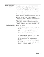
Brief
Description
of
the
4291B
F
or
surface-mount
component
evaluation
and
material
testing,
the
4291B
RF
Impedance/Material
Analyzer
is
an
integrated
package
designed
to
provide
accurate
testing
at
higher
frequencies
.
F
or
component
manufacturers
,
RF
and
digital
equipment
designers
,
and
material
researchers
,
the
4291B
provides
these
capabilities:
Broad
frequency
coverage
from
1
MHz
to
1.8
GHz
for
testing
RF
components
and
materials
.
Improved
measurement
accuracy
and
repeatability
over
an
impedance
range
of
0.1
to
50
k
Surface-mount-device
(SMD)
test
xtures
for
dierent
sizes
of
chip
capacitors
and
inductors
.
Dielectric
test
xture
and
built-in
function
for
measuring
permittivity
,
including
Cole-Cole
plot
relaxation
time
(with
Option
002
and
16453A ).
Magnetic
test
xture
and
built-in
function
for
measuring
permeability
of
ferrite
material
(with
Option
002
and
16454A ).
Direct
impedance
and
material
parameter
measurement
versus
time
,
humidity
,
or
temperature
(with
an
external
temperature
chamber).
A
dditional
F
eatures
Impedance
Measurement
Evaluate
components
with
dc
bias
up
to
6100
mA
and
640
V
(with
Option
001).
(See
\Applying
Dc
Bias
(Option
001
Only)"
in
Chapter
6.)
Monitor
test
signals
applied
to
your
DUT
s
.
(See
\Monitoring
the
OSC
Level
or
the
Dc
Bias
Level"
in
Chapter
6.)
Simulate
a
component
with
equivalent
circuit
analysis
.
(See
\Equivalent
Circuit
Analysis"
in
Chapter
3.)
Others
Store
the
measurement
data
and
analyzer's
settings
on
the
DOS
and
LIF
compatible
1.4
MB
oppy
disk
drive
and
memory
disk.
(See
\Saving
and
Recalling"
in
Chapter
6.)
Markers
and
marker
utilities
(See
\Using
the
Marker"
in
Chapter
6.)
Limit
lines
for
go/no-go
testing
(See
\P
erforming
a
GO/NO-GO
T
est"
in
Chapter
6.)
Frequency
linear/log/list
sweep
(See
\P
erforming
a
List
Sweep
Measurement"
in
Chapter
6
for
list
sweep
.)
Introduction
1-3
Summary of Contents for 4291B
Page 20: ......
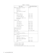
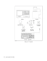
Page 24: ...Figure 2 1 Contents 2 4 Installation and Set Up Guide ...
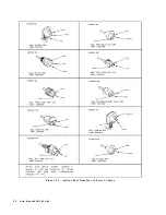
Page 26: ...Figure 2 2 Agilent Part Numbers of Power Cables 2 6 Installation and Set Up Guide ...
Page 34: ...Figure 2 7 Connecting a Keyboard 2 14 Installation and Set Up Guide ...
Page 60: ......
Page 104: ......
Page 130: ......
Page 152: ......
Page 158: ......


