2.
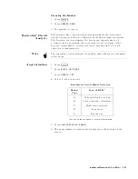
Press
NNNNNNNNNNNNNNNNNNNNNNNNNNNNNNNNNNNNNN
DONE:
COMPEN
.
3.
V
erify
that
two
\CMP "
notations
appear
on
the
left
side
of
the
display
.
Note
Y
ou
can
do
each
compensation
over
again.
Press
4
Cal
5
N
NNNNNNNNNNNNNNNNNNNNNNNNNNNNNNNNNNNNNNNNNNN
FIXTURE
COMPEN
NNNNNNNNNNNNNNNNNNNNNNNNNNNNNNNNNNNNNNNNNNNNNNNNNNNNNNNNNNN
RESUME
CAL
SEQUENCE
and
do
compensations
only
you
need
again.
Note
Y
ou
have
to
set
an
electrical
length
value
on
4291B
before
executing
compensations
except
for
load
compensation.
If
you
change
the
electrical
length
value
,
you
have
to
retry
xture
compensations
except
for
load
compensation.
6.
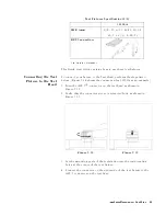
Connecting
the
DUT
to
the
T
est
Fixture
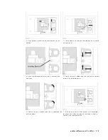
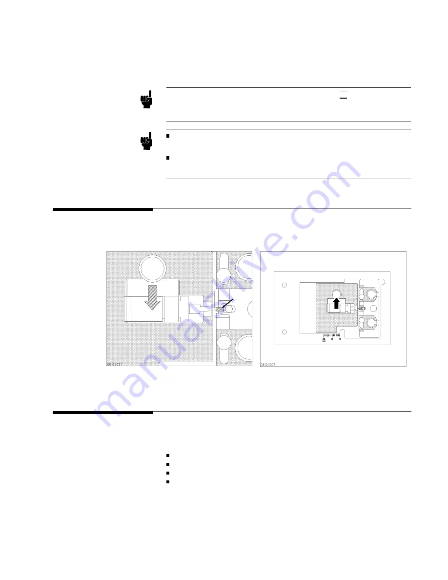
How
to
connect
the
DUT
to
the
16192A
is
shown
in
below
as
an
example
.
The
procedures
for
the
16191A
and
16193A
are
shown
in
Appendix
C.
1.
Push
the
lever
and
place
the
DUT
on
the
electrode
.
2.
Release
the
lever
to
hold
the
DUT
.
7.
Setting
up
the
Analyzer
Before
you
start
the
measurement,
you
must
set
up
the
analyzer
to
t
your
measurement
requirements
.
This
section
provides
the
set
up
procedures
for
the
following
measurements:
Frequency
characteristics
of
j Zj -
Frequency
characteristics
of
C-D
OSC
level
characteristics
of
C-D
dc
bias
voltage
characteristics
of
C-D
The
set
up
procedure
for
each
measurement
is
described
in
the
following
pages
.
Set
up
your
analyzer
according
the
applicable
procedure
.
Impedance
Measurement
Quick
Start
3-15
Summary of Contents for 4291B
Page 20: ......
Page 24: ...Figure 2 1 Contents 2 4 Installation and Set Up Guide ...
Page 26: ...Figure 2 2 Agilent Part Numbers of Power Cables 2 6 Installation and Set Up Guide ...
Page 34: ...Figure 2 7 Connecting a Keyboard 2 14 Installation and Set Up Guide ...
Page 60: ......
Page 104: ......
Page 130: ......
Page 152: ......
Page 158: ......


