120
Chapter 5
Setting Measurement Conditions
Sweeping Multiple Sweep Ranges with Different Conditions in a Single
Action (List Sweep)
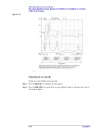
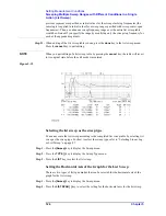
The above setting will add a new value for the sweep stop or span frequency to the cell
located in the segment raw and the sweep stop/span frequency column (START or
CENTER) of the list sweep table in editing mode.
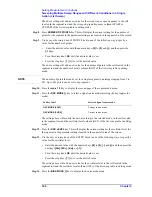
Step 8.
Press
NUMBER OF POINTS
key. This will display the current setting for the number of
points for the segment in the parameter settings area located in the upper left of the screen.
Step 9.
Use keys or the rotary knob of ENTRY block in one of the following way to specify a
value for the number of points.
•
Enter the desired value with the numeric keys (
[0]
to
[9]
, and
[.]
) and then press the
[
´
1]
key.
•
Turn the rotary knob (
m
m
m
m
) until the desired value is set.
•
Press the step keys ([
][
¯
]) to set the desired value.
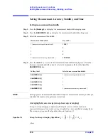
The above setting will add a new value for the number of points to the cell located in the
segment row and the number of points column (NOP) of the list sweep table in editing
mode.
NOTE
The number of points that can be set for a single segment is an integer ranging from 2 to
201. Up to 801 points can be set to any segment.
Step 10.
Press the
more 1/3
key to display the second page of the segment edit menu.
Step 11.
Press the
OSC MODE [ ]
key to select a signal source mode (pressing the key toggles the
mode).
The setting above will modify the unit, according to the selected mode, in the cell located
in the segment row and the oscillator level column (OSC) of the list sweep table in editing
mode.
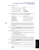
Step 12.
Press the
OSC LEVEL
key. This will display the current setting for the oscillator level for
the segment in the parameter settings located in the upper left area of the screen.
Step 13.
Use the keys or rotary knob of the ENTRY block in one of the following ways to specify a
value for the oscillator level.
•
Enter the desired value with the numeric keys (
[0]
to
[9]
,
[.]
, and
[-]
) and then press the
unit key (
[G/n]
,
[M/
m
]
,
[k/m]
, or
[
´
1]
).
•
Turn the rotary knob (
m
m
m
m
) until the desired value is set.
•
Press the step keys ([
][
¯
]) to set the desired value.
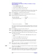
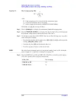
The setting above will add a new value for the oscillator level to the cell located in the
segment row and the oscillator level column (OSC) of the list sweep table in editing mode.
Step 14.
Press the
BIAS MODE [ ]
key to display the dc bias mode menu.
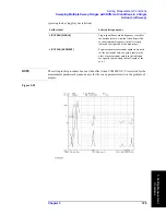
Softkey label
Selected signal source mode
OSC MODE [VOLT]
Voltage source mode
OSC MODE [CURR]
Current source mode
Summary of Contents for 4294A
Page 1: ......
Page 2: ......
Page 4: ......
Page 5: ......
Page 6: ......
Page 8: ......
Page 16: ...8 ...
Page 30: ...22 Chapter1 Installation Power Cable Figure 1 2 Alternative Power Cable Options ...
Page 70: ...62 Chapter3 Front Rear Panel and LCD Display Items Displayed on the LCD ...
Page 436: ...428 AppendixB Key Definitions Softkeys displayed by pressing the Recall key ...
Page 454: ...446 AppendixC Error messages WRONG I O PORT DIRECTION ...
Page 468: ......


