Chapter 7
195
Setting Up the Display of Measurement Results
Monitoring the dc Bias Level
7. S
ett
ing
Up t
he Di
sp
la
y o
f
M
eas
ur
em
ent Res
ult
s
Step 5.
If the sweep cycle is currently in the hold state, specify the number of sweep cycles (see
“Specifying Sweep Times and Stopping Sweep” on page 114) and then start testing the
DUT by specifying the trigger source (see “Selecting a Method to Start Measurement
(Trigger Source)” on page 111). Alternatively, you can use the continuous sweep mode by
implementing a free run trigger.
NOTE
Marker-based level monitoring takes effect when you start a new sweep cycle after turning
on the dc bias level monitor feature.
Step 6.
Press the
[Utility]
key to display the Utility menu. The main marker appears on the trace if
it is not already displayed.
Step 7.
Press the
LEVEL MON [ ]
key to display the Level Monitor menu.
Step 8.
Traces A and B are each associated with a field called “Marker Statistics/Trace Bandwidth
Analysis” that is used to display the dc bias level monitored at the marker position when
the corresponding trace is active. To activate Trace A or B, press the appropriate key:
Step 9.
To set up marker-based level monitoring, press one of the following keys:
NOTE
The setting you select for marker-based monitoring must match the setting for dc bias level
monitoring (step 4).
Step 10.
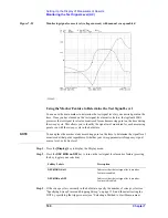
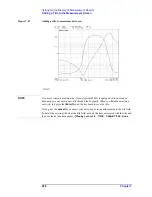
Move the main marker to your desired measuring point on the trace. The Marker
Statistics/Trace Bandwidth Analysis field for the activate trace indicates the test signal
level monitored at the marker position.
NOTE
Marker-based monitoring works using the same mechanism as, but provides level values in
higher resolution (more digits) than, real-time monitoring (described in “Monitoring the dc
Bias Level on a Real-time Basis” on page 193).
Although marker-based level monitoring uses separate display fields for Traces A and B, it
does not depend on the active trace and provides the same level value regardless of which
Monitor the dc bias voltage level
VOLT
Monitor the dc bias current level
CURRENT
To activate:
Press:
Trace A
[A]
Trace B
[B]
To:
Press:
Turn off marker-based level monitoring
OFF
Monitor the dc bias voltage level
DC-V
Monitor the dc bias current level
DC-I
To: Press:
Summary of Contents for 4294A
Page 1: ......
Page 2: ......
Page 4: ......
Page 5: ......
Page 6: ......
Page 8: ......
Page 16: ...8 ...
Page 30: ...22 Chapter1 Installation Power Cable Figure 1 2 Alternative Power Cable Options ...
Page 70: ...62 Chapter3 Front Rear Panel and LCD Display Items Displayed on the LCD ...
Page 436: ...428 AppendixB Key Definitions Softkeys displayed by pressing the Recall key ...
Page 454: ...446 AppendixC Error messages WRONG I O PORT DIRECTION ...
Page 468: ......


