236
Chapter 8
Analysis and Processing of Result
Analyze trace bandwidth
Analyze trace bandwidth
The Agilent 4294A can automatically derive the parameters called bandwidth, center
value, Q value, peak,
D
L, and
D
R from the measurement trace.
At the instant when the trace bandwidth analysis function is turned on and at the
completion of each subsequent sweep, cutoff points are searched for on the sweep
parameter value axis, starting from the main marker position at that time and advancing in
both directions. When two cutoff points are detected, six parameters (bandwidth (width),
center value (center), Q, peak (peak),
D
L, and
D
R) are derived from the data at those points
and displayed in the Marker Statistics/Trace Bandwidth Analysis Result field on the right
of the screen.
NOTE
The peak (peak), one of the six parameters displayed on the screen as trace bandwidth
analysis results, is the first position of the main marker itself. Therefore, before executing
the trace bandwidth analysis, use the peak search function and so on to move the main
marker to the peak on the trace as necessary.
The cutoff points are searched for according to the definition specified by the user. For how
to define the cutoff points, refer to Appendix , “Define the cutoff point in trace bandwidth
analysis,” on page 238.
The definitions of the six parameters displayed on the screen as the final results also vary
depending on the delta marker mode selected at the time. For how to set the delta marker
mode, refer to “Setting the delta marker in the trace bandwidth analysis” on page 239.
Definitions of parameters in the trace bandwidth analysis
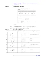
Table 8-2 shows the definition of each parameter in the trace bandwidth analysis.
Table 8-2
Definitions of parameters in trace bandwidth analysis
Parameter
Definition
Cutoff point
Two points having the predefined measurement parameter
value that are searched for and detected from the main
marker position to both ends on the trace. You define the
measurement parameter value of the cutoff points by
selecting, assuming that the measurement parameter value
of the main marker position is MKRVAL,
,
,
or a user entered value (fixed
value). For more information on the procedure of the
definition, refer to “Define the cutoff point in trace
bandwidth analysis” on page 238. At the detected cutoff
points, the sub-markers numbered 2 and 3 will be placed.
MKRVAL
2
-------------------------
MKRVAL
2
´
MKRVAL
2
-------------------------
Summary of Contents for 4294A
Page 1: ......
Page 2: ......
Page 4: ......
Page 5: ......
Page 6: ......
Page 8: ......
Page 16: ...8 ...
Page 30: ...22 Chapter1 Installation Power Cable Figure 1 2 Alternative Power Cable Options ...
Page 70: ...62 Chapter3 Front Rear Panel and LCD Display Items Displayed on the LCD ...
Page 436: ...428 AppendixB Key Definitions Softkeys displayed by pressing the Recall key ...
Page 454: ...446 AppendixC Error messages WRONG I O PORT DIRECTION ...
Page 468: ......


