252
Chapter 8
Analysis and Processing of Result
Calculate the equivalent circuit parameter and simulate the frequency
characteristics
When the equivalent circuit parameter has been calculated based on the result of sample
measurement, we recommend that frequency characteristics be simulated based on the
equivalent circuit parameter by following the procedures to “Simulate the frequency
characteristics based on the equivalent circuit parameter” (below). The adequacy of the
selected equivalent circuit and validity of the parameter calculation result can be verified
by comparison between the frequency characteristics of the actual sample and the
simulation result.
To calculate the equivalent circuit parameter for a resonator, another possible method, in
addition to the method of equivalent circuit analysis used in the equivalent circuit E
discussed above, is to use the specifically designed GP-IB command. For details, see
Programming Manual
.
Simulate the frequency characteristics based on the equivalent circuit
parameter
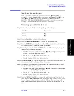
Simulate the frequency characteristics according to the following steps:
NOTE
Start from Step 12 when you want to simulate the frequency characteristics on the basis of
the equivalent circuit parameter calculated according to the procedure of “Calculate the
equivalent circuit parameter based on the measurement result” on page 249.
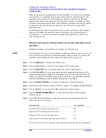
Step 1.
Press the
[Display]
key to display the Display menu.
Step 2.
Press the
more 1/2
key to display the second page of the Display menu.
Step 3.
Press the
EQUIV CKT
key to display the Equivalent Circuit Analysis menu.
Step 4.
Press the
CKT on OFF
key to turn on the equivalent circuit diagram indication function. The
equivalent circuit diagram, instead of the measurement trace, is shown on the screen. This will
enable you to check the equivalent circuit to be selected in the next step. It should be noted that
equivalent circuit analysis is enabled without having to turn on this display.
Step 5.
Press the
SELECT CIRCUIT
key to display the Equivalent Circuit Select menu.
Step 6.
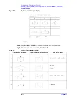
Select the equivalent circuit according to Table 8-3 on page 250 (using keys
A
,
B
,
C
,
D
and
E
).
Step 7.
Press the
return
key to go back to the Equivalent Circuit Analysis menu.
Step 8.
Press the
DEFINE PARAMETERS
key to display the Equivalent Circuit Parameter
Definition menu.
Step 9.
Use the
R1
,
C1
,
L1
and
C0
keys to select the equivalent circuit parameter where the
numerical value is to be entered.
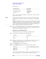
The current set value of the equivalent circuit parameter is displayed in the set parameter
Key operation
Key operation
Resistance of R1 of selected equivalent circuit
R1
Capacitance of C1 of selected equivalent circuit
C1
Inductance of L1 of selected equivalent circuit
L1
Capacitance of C0 when the equivalent circuit E is selected
C0
Summary of Contents for 4294A
Page 1: ......
Page 2: ......
Page 4: ......
Page 5: ......
Page 6: ......
Page 8: ......
Page 16: ...8 ...
Page 30: ...22 Chapter1 Installation Power Cable Figure 1 2 Alternative Power Cable Options ...
Page 70: ...62 Chapter3 Front Rear Panel and LCD Display Items Displayed on the LCD ...
Page 436: ...428 AppendixB Key Definitions Softkeys displayed by pressing the Recall key ...
Page 454: ...446 AppendixC Error messages WRONG I O PORT DIRECTION ...
Page 468: ......


