Chapter 8
257
Analysis and Processing of Result
Set a limit to the trace and make pass/fail evaluation
8. A
nal
ys
is
a
nd P
roc
es
si
ng
of
Res
ult
Step 2.
Activate the trace for testing the limit line.
Step 3.
Press the
[Marker]
key to display the main marker on the trace.
NOTE
The limit line table can be set without displaying the marker. However, the presence of a
marker will be convenient for your work because it allows the numerical value on the trace
to be read and the marker position to be used to enter the limit line set value.
Step 4.
Press the
[System]
key to display the System menu.
Step 5.
Press the
LIMIT TEST
key to display the Limit Test menu.
Step 6.
Press the
EDIT LIMIT LINE
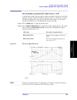
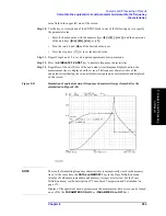
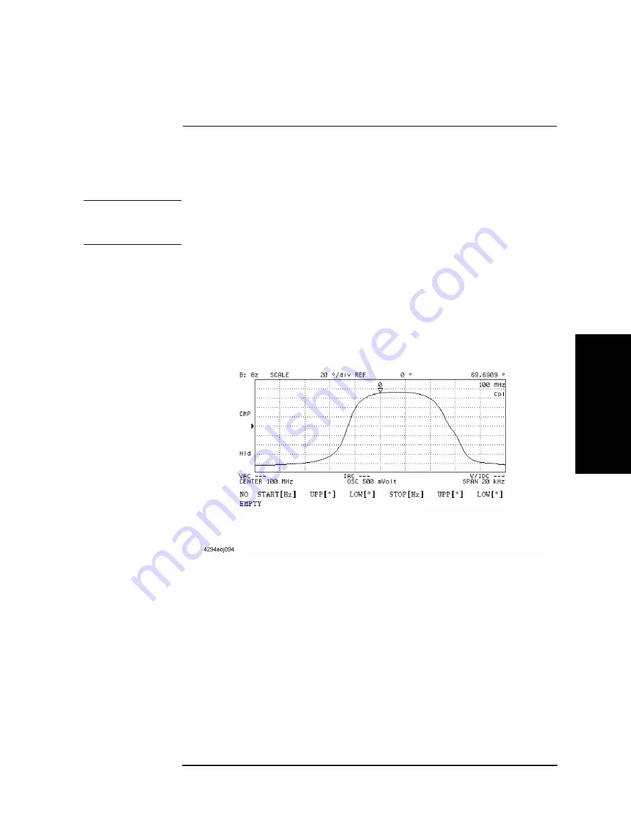
key to invoke the limit line edit mode. This also displays the
Limit Line Edit menu.
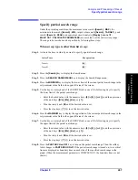
Figure 8-24
Limit line edit mode
Step 7.
Press the
ADD
key and add a new segment to the limit line table. This also displays the
Segment Edit menu. The initial value is input in advance to the segment added to the limit
line table.
Step 8.
Press the
START
key. The current start value of the segment is displayed in the upper left
area of the screen.
Step 9.
Use the keys or rotary knob of the ENTRY block in one of the following ways to specify
the segment start value.
•
Enter the desired value with the numeric keys (
[0]
to
[9]
,
[-]
and
[.]
) and then press one
of the unit keys (
[G/n]
,
[M/
m
]
,
[k/m]
, or
[
´
1]
).
•
Turn the rotary knob (
m
m
m
m
) until the desired value is set.
Active Trace
Key operation
Trace A
[A]
Trace B
[B]
Summary of Contents for 4294A
Page 1: ......
Page 2: ......
Page 4: ......
Page 5: ......
Page 6: ......
Page 8: ......
Page 16: ...8 ...
Page 30: ...22 Chapter1 Installation Power Cable Figure 1 2 Alternative Power Cable Options ...
Page 70: ...62 Chapter3 Front Rear Panel and LCD Display Items Displayed on the LCD ...
Page 436: ...428 AppendixB Key Definitions Softkeys displayed by pressing the Recall key ...
Page 454: ...446 AppendixC Error messages WRONG I O PORT DIRECTION ...
Page 468: ......

