background image

Making

a

Measurement

4338B

T

o

Display

Deviation

Data

The

1

before

the

measurement

parameter

on

the

LCD

display

tells

that

the

displayed

value

for

the

parameter

is

the

deviation

value

.

T

o

Set

the

Reference

V

alue

1.

Press

.

The

following

menu

is

displayed.

2.

Press

or

to

select

1RefEnt ,

and

press

.

T

o

set

by

measuring

the

reference

DUT:

a.

Press

regardless

of

the

trigger

mode

,

and

the

primary

parameter

is

measured.

Press

to

set

the

measurement

value

as

the

primary

reference

.

b.

Then

the

secondary

parameter

reference

setting

menu

(1Ref

Secondary=

)

is

displayed.

Press

to

measure

the

secondary

parameter

,

and

press

to

set

the

measurement

value

as

the

secondary

reference

.

T

o

set

by

entering

a

value:

a.

Enter

the

primary

parameter

reference

value

using

the

numeric

keys

,

and

press

.

When

you

want

to

exit

without

changing

value

,

just

press

.

b.

Enter

the

secondary

parameter

reference

value

using

the

numeric

keys

,

and

press

.

When

you

want

to

exit

without

changing

value

,

just

press

.

2-8

Operating

the

4338B

Artisan Technology Group - Quality Instrumentation ... Guaranteed | (888) 88-SOURCE | www.artisantg.com

Summary of Contents for 4338B

Page 1: ... underutilized and idle equipment along with credit for buybacks and trade ins Custom engineering so your equipment works exactly as you specify Critical and expedited services Leasing Rentals Demos In stock Ready to ship TAR certified secure asset solutions Expert team I Trust guarantee I 100 satisfaction All trademarks brand names and brands appearing herein are the property of their respective ...

Page 2: ... 0 000018 k 57 Change 2 Add TAR in Resistance Measurement Accuracy Test Page 9 10 to the following Standard ohm Test Signal Current A Test Limits ohm Test Result ohm Measurement Uncertainty ohm TAR 1 m 10 m 0 024 m 0 0081 m 2 9 10 m 10 m 0 054 m 0 025 m 2 2 100 m 1 m 0 45 m 0 18 m 2 6 1 10 m 0 0043 0 0020 2 1 10 10 μ 0 044 0 017 2 6 100 1 μ 0 49 0 15 3 3 1 k 10 μ 9 3 0 0019 k 5 0 10 k 1 μ 540 0 02...

Page 3: ...certainty Hz 1 k 1 0 000018 k Change 2 Change the Measurement Uncertainty value of Resistance Measurement Accuracy Test Page 9 10 to the following Standard ohm Test Signal Current A Test Limits ohm Test Result ohm Measurement Uncertainty ohm 1 m 10 m 0 024 m 0 0081 m 10 m 10 m 0 054 m 0 025 m 100 m 1 m 0 45 m 0 18 m 1 10 m 0 0043 0 00020 10 10 μ 0 044 0 017 100 1 μ 0 49 0 15 1 k 10 μ 9 3 0 0019 k ...

Page 4: ...c line frequency is not match there s any possibility the measurement error will rise Make sure the ac line frequency has been set up correctly Change 2 Add the following condition to the Measurement Accuracy page 8 3 3 The ac line frequency has been set up correctly C Copyright 2007 Agilent Technologies Artisan Technology Group Quality Instrumentation Guaranteed 888 88 SOURCE www artisantg com ...

Page 5: ...さい 注記 AC 電源周波数の設定値が一致していない場合 測定誤差が増大する可能性があります 必ず AC 電源周波数 を正しく設定して下さい 変更 2 測定確度の条件 ページ 8 3 に以下の条件を追加して下さい 3 AC 電源周波数が正しく設定されている C Copyright 2007 Agilent Technologies Artisan Technology Group Quality Instrumentation Guaranteed 888 88 SOURCE www artisantg com ...

Page 6: ...Artisan Technology Group Quality Instrumentation Guaranteed 888 88 SOURCE www artisantg com ...

Page 7: ...Artisan Technology Group Quality Instrumentation Guaranteed 888 88 SOURCE www artisantg com ...

Page 8: ...Artisan Technology Group Quality Instrumentation Guaranteed 888 88 SOURCE www artisantg com ...

Page 9: ...repairing the instrument there is a potential fire or shock hazard for the operator n Instrument operates abnormally n Instrument emits abnormal noise smell smoke or a spark like light during the operation n Instrument generates high temperature or electrical shock during operation n Power cable plug or receptacle on instrument is damaged n Foreign substance or liquid has fallen into the instrumen...

Page 10: ...Artisan Technology Group Quality Instrumentation Guaranteed 888 88 SOURCE www artisantg com ...

Page 11: ...Artisan Technology Group Quality Instrumentation Guaranteed 888 88 SOURCE www artisantg com ...

Page 12: ...Artisan Technology Group Quality Instrumentation Guaranteed 888 88 SOURCE www artisantg com ...

Page 13: ...ion Do not apply DC voltage exceeding 42V to the UNKNOWN terminals or input circuit of the 4338B will be destroyed Artisan Technology Group Quality Instrumentation Guaranteed 888 88 SOURCE www artisantg com ...

Page 14: ...Artisan Technology Group Quality Instrumentation Guaranteed 888 88 SOURCE www artisantg com ...

Page 15: ...th serial number pre x JP1KD or rmware revision 1 01 For additional important information about serial numbers read Serial Number in Appendix A Agilent Part No 04338 90040 Printed in Japan March 2003 Seventh Edition Artisan Technology Group Quality Instrumentation Guaranteed 888 88 SOURCE www artisantg com ...

Page 16: ...ment may be photocopied reproduced or translated to another language without the prior written consent of the Agilent Technologies Agilent Technologies Japan Ltd Component Test PGU Kobe 1 3 2 Murotani Nishi ku Kobe shi Hyogo 651 2241 Japan c Copyright 1996 1997 1998 2000 2001 2002 2003 Agilent Technologies Japan Ltd Artisan Technology Group Quality Instrumentation Guaranteed 888 88 SOURCE www arti...

Page 17: ...tensive technical changes are incorporated March 1996 First Edition part number 04338 90010 April 1997 Second Edition part number 04338 90020 June 1998 Third Edition part number 04338 90030 January 2000 Fourth Edition part number 04338 90030 January 2001 Fifth Edition part number 04338 90030 September 2002 Sixth Edition part number 04338 90030 March 2003 Seventh Edition part number 04338 90040 iii...

Page 18: ...ment in the presence of ammable gasses or fumes Operation of any electrical instrument in such an environment constitutes a de nite safety hazard Keep Away From Live Circuits Operating personnel must not remove instrument covers Component replacement and internal adjustments must be made by quali ed maintenance personnel Do not replace components with the power cable connected Under certain condit...

Page 19: ...r chassis terminal A connection to the frame chassis of the equipment which normally include all exposed metal structures This Warning sign denotes a hazard It calls attention to a procedure practice condition or the like which if not correctly performed or adhered to could result in injury or death to personnel This Caution sign denotes a hazard It calls attention to a procedure practice conditio...

Page 20: ...gies Buyer shall prepay shipping charges to Agilent Technologies and Agilent Technologies shall pay shipping charges to return the product to Buyer However Buyer shall pay all shipping charges duties and taxes for products returned to Agilent Technologies from another country Agilent Technologies warrants that its software and rmware designated by Agilent Technologies for use with an instrument wi...

Page 21: ...r based on contract tort or any other legal theory Assistance Product maintenance agreements and other customer assistance agreements are available for Agilent Technologies products For any assistance contact your nearest Agilent Technologies Sales and Service O ce Addresses are provided at the back of this manual vii Artisan Technology Group Quality Instrumentation Guaranteed 888 88 SOURCE www ar...

Page 22: ...in place of the words in italics For example copy lename means to type the word copy to type a space and then to type the name of a le such as file1 Computer Computer font is used for on screen prompts and messages 4HARDKEYS5 Labeled keys on the instrument front panel are enclosed in 4 5 NNNNNNNNNNNNNNNNNNNNNNNNNN SOFTKEYS Softkeys located to the right of the CRT are enclosed in NNNNN viii Artisan...

Page 23: ...1 14 Toggle Keys 1 14 Selection Keys 1 14 Value Setup Keys 1 15 Numeric Keys 1 15 Maximum and Minimum Keys 1 16 Left Down and Right Up Arrow Keys 1 17 Back Space Key 1 17 To Perform a Measurement 1 18 Connecting a Test Fixture 1 19 Using the 16338A 1 19 To Reset 4338B 1 20 To Perform a SHORT Correction 1 20 To Select Measurement Parameter 1 22 To Select Auto Measurement Mode 1 22 To Select Test Si...

Page 24: ...l Mode 2 12 To Set the GPIB Address 2 12 To Print Measurement Data 2 12 To Test the 4338B 2 13 To Perform a Self Test 2 13 To Test the Front Panel Keys Functionality 2 13 If You Have a Problem 2 14 If the Display is Blank and the 4338B Appears Dead 2 14 If an Error Message is Displayed 2 14 If the 4338B does not Accept Any Key Input 2 14 3 Function Reference Introduction 3 1 Front Panel 3 2 Displa...

Page 25: ...rial Number Plate 3 15 Power Cord Receptacle 3 15 Power Code 3 15 Handler Interface 3 16 Speci cation 3 16 GPIB Interface 3 18 Theory of Operation 3 20 Overall Measurement Theory 3 20 Test Signal Level 3 22 Actual Signal Level across DUT 3 22 Limitation of Test Level 3 22 4 Remote Operation Introduction 4 1 Getting Started 4 2 Input Output Statements 4 2 Reading the GPIB Address 4 2 Sending a Remo...

Page 26: ...d 4 18 To Retrieve Data E ciently 4 22 To Use a Data Bu er 4 22 Other Features 4 23 To test the 4338B 4 23 To Report the Instrument s Status 4 23 If You Have a Problem 4 25 If the 4338B Hangs Up When You Send ABORt Command 4 25 5 GPIB Reference Introduction 5 1 GPIB Commands 5 1 Common Commands 5 1 Subsystem Commands 5 1 Subsystem Command Tree 5 4 Program Message Syntax 5 5 Case 5 5 Program Messag...

Page 27: ...iate IMMediate 5 21 INITiate CONTinuous f ON j OFF j 1 j 0 g 5 21 SENSe Subsystem 5 22 SENSe AVERage COUNt numeric value 5 22 SENSe AVERage STATe f ON j OFF j 1 j 0 g 5 22 SENSe CORRection COLLect ACQuire STANdard2 5 22 SENSe CORRection COLLect METHod REFL1 5 23 SENSe CORRection DATA STANdard2 5 23 SENSe CORRection STATe f ON j OFF j 1 j 0 g 5 23 SENSe FIMPedance APERture numeric value MSjS 5 23 S...

Page 28: ...e 5 32 3SRE 5 32 3STB 5 33 3TRG 5 33 3TST 5 33 3WAI 5 33 Status Reporting Structure 5 34 Service Request SRQ 5 34 Status Byte Resister 5 35 Standard Event Status Register 5 36 Standard Operation Status Group 5 37 Operation Status Register 5 38 Questionable Status Register 5 38 Trigger System 5 39 4338B Trigger System Con guration 5 39 Idle State 5 39 Initiate State 5 40 Event Detection State 5 40 ...

Page 29: ...ation 9 4 Test Equipment 9 4 Procedure 9 4 Resistance Measurement Accuracy Test 9 6 Speci cation 9 6 Test Equipment 9 6 Procedure 9 6 Calculation Sheet 9 9 Test Signal Frequency Accuracy Test 9 9 Resistance Measurement Accuracy Test 9 9 Performance Test Record 9 10 Test Signal Frequency Accuracy Test 9 10 Resistance Measurement Accuracy Test 9 10 Functional Test 9 11 Introduction 9 11 Test Equipme...

Page 30: ... B 1 Electrical Characteristics B 1 Output Signals B 1 Input Signals B 4 Setting Up the Handler Interface Board B 5 Tools and Fasteners B 5 Procedure B 5 C Overload Over Voltage No Contact Operations Messages Instrument Errors Messages 2 GPIB Errors Messages 3 Index Contents 8 Artisan Technology Group Quality Instrumentation Guaranteed 888 88 SOURCE www artisantg com ...

Page 31: ...nsfer format using the FETC command 4 19 4 7 Reading out measured result in binary transfer format using FETC command 4 21 5 1 Proper Use of the Colon and Semicolon 5 4 5 2 Status Reporting Structure 5 34 5 3 Status byte Register 5 35 5 4 Standard Event Status Register 5 36 5 5 Standard Operation Status Group Structure 5 37 5 6 Trigger System Con guration 5 39 5 7 Inside an Event Detection State 5...

Page 32: ...ace Control Output Signals Diagram B 3 B 3 Handler Interface Input Signal Diagram B 4 B 4 A1 Main Board Location B 7 Contents 10 Artisan Technology Group Quality Instrumentation Guaranteed 888 88 SOURCE www artisantg com ...

Page 33: ...ister Assignments 5 38 5 7 Questionable Status Register Assignments 5 38 8 1 Measurement Accuracy 8 4 9 1 Required Equipment 9 1 9 2 Resistance Measurement Accuracy Test Settings 9 8 9 3 9 13 A 1 Manual Changes by Serial Number A 1 A 2 Manual Changes by ROM Version A 1 B 1 Handler Output Electrical Characteristics B 1 B 2 Handler Input Electrical Characteristics B 4 B 3 Pull up Resister Locations ...

Page 34: ...Artisan Technology Group Quality Instrumentation Guaranteed 888 88 SOURCE www artisantg com ...

Page 35: ...illiohmmeter This chapter discusses the following topics Overview Incoming Inspection Ventilation Requirements Instruction for Cleaning Power Cable Preparation for Use Using Front Panel Keys Basic Operation Getting Started 1 1 Artisan Technology Group Quality Instrumentation Guaranteed 888 88 SOURCE www artisantg com ...

Page 36: ...e testing of relays switches connectors PC board traces and cables The 1 kHz test signal eliminates potential errors introduced by thermo electric e ects across the DUT contacts The 1 kHz ac test signal is the best solution for evaluating the internal resistance of batteries because it avoids dc energy consumption High Speed Measurements The high speed 34 ms built in comparator and GPIB handler in...

Page 37: ... clip 16006A Pin Type Probe Lead 0 4 m 16007A Alligator Clip Leads 0 4 m with 2 red clips 16007B Alligator Clip Leads 0 4 m with 2 black clips 16143B Mating Cable 0 6 m 16064B LED Display Trigger Box pass fail display and trigger Getting Started 1 3 Artisan Technology Group Quality Instrumentation Guaranteed 888 88 SOURCE www artisantg com ...

Page 38: ...ment Indicator turns ON when Auto Measurement is enabled and OFF when disabled 7 Measurement Parameter Key sets measurement parameter to be displayed Shift Deviation Mode Key enables the deviation measurement function 8 Show Setting Key changes the mode of Measurement Settings display Shift Display Mode Key selects the display mode 9 Auto Hold Range Key selects the Auto or Hold range mode Shift Ra...

Page 39: ...or Lower Limit Sec Low Key sets the lower limit of the comparator function for the secondary comparator 20 0 Key Shift Key Lock Key locks out all key input except for this key 21 Key Shift Reset Key resets the 4338B to its default state 22 0 Key Shift Con guration Key sets the beep setting and power line frequency setting and executes the internal test 23 3 Key 24 2 Key Shift Contact Check Key tog...

Page 40: ...ineering units p n m k and M 34 Back Space Key erases the last entered character when entering numeric values 35 Enter Key terminates key entry 1 6 Getting Started Artisan Technology Group Quality Instrumentation Guaranteed 888 88 SOURCE www artisantg com ...

Page 41: ...mode When in the Auto range mode the Hold range annunciator is not displayed d Hold level indicates that the 4338B is in the Hold level mode When in the Auto level mode the Hold level annunciator is not displayed e Comparator On indicates that comparator function is ON f Contact Check On indicates that the contact check function is ON g Talk Only indicates that the 4338B is in the GPIB talk only m...

Page 42: ...used to synchronize timing with an external handler 3 EXT TRIGGER Terminal is used to input an external trigger signal 4 Serial Number Plate gives the instrument s manufacturing information 5 Line Voltage Selector used to set the 4338B s line voltage setting to the voltage of the ac power source 6 Power Cord Receptacle 7 LINE Fuse Holder 1 8 Getting Started Artisan Technology Group Quality Instrum...

Page 43: ...learance to dissipate heat at installation site To ensure the speci cations and measurement accuracy of the product you must keep ambient temperature around the product within the speci ed range by providing appropriate cooling clearance around the product or for the rackmount type by forcefully air cooling inside the rack housing For information on ambient temperature to satisfy the speci cations...

Page 44: ... cable shipped with each instrument depends on the country of destination Refer to Figure 1 1 for the part numbers of the power cables available Warning For protection from electrical shock the power cable ground must not be defeated The power plug must be plugged into an outlet that provides a protective earth ground connection 1 10 Getting Started Artisan Technology Group Quality Instrumentation...

Page 45: ...4338B Overview Figure 1 1 Power Cable Supplied Getting Started 1 11 Artisan Technology Group Quality Instrumentation Guaranteed 888 88 SOURCE www artisantg com ...

Page 46: ...match your power line voltage When your power line voltage is 100 120 Vac 610 slide the Selector to 115 V When your power line voltage is 220 240 Vac 610 slide the Selector to 230 V See Figure 1 2 Fuse Use the fuse shown in Table 1 1 If you require the fuse contact the nearest Agilent Technologies sales o ce The fuse can be replaced by turning the fuse holder shown in Figure 1 2 counterclockwise u...

Page 47: ...he power line frequency setting is correct a Press The following menu is displayed b Press until the Line blinks then Press A blinking item is selected c If the setting does not match the ac line frequency press to toggle the setting between 50 Hz and 60 Hz d Press two times to exit this menu The power line frequency setting is stored and does not change after reset or on power o Once you set it y...

Page 48: ...n several conditions An annunciator will indicate the current condition For example Press and the Meas Time annunciator 9 alternately points to the current setting Short Med or Long Selection Keys Pressing a selection key will display the selection display The blinking item is the one currently selected By using or the selection key itself the selected blinking items can be changed For example to ...

Page 49: ...e can be altered by using the following keys Numeric Keys Maximum and Minimum Keys Left Down and Right Up Arrow Keys Back Space Key Numeric Keys Some commands use numeric parameters A numeric parameter is the actual value used by the 4338B For example to set the averaging rate to 10 1 Press 2 Press Getting Started 1 15 Artisan Technology Group Quality Instrumentation Guaranteed 888 88 SOURCE www a...

Page 50: ...value and exit this menu Note Before you press the previous setting is still the current setting even though the displayed value has changed If you press a key other than one of the keys in ENTRY block before pressing the setting will not change and the displayed value will be discarded Maximum and Minimum Keys These keys enter the maximum and minimum numeric value in place of using the numeric ke...

Page 51: ...2 Press several times and con rm a change in value 3 Press to exit the setup display Back Space Key Erases the last entered character and cancels the input value For example 1 Press to select comparator limit menu 2 Press 3 Press Last entered 4 is erased Getting Started 1 17 Artisan Technology Group Quality Instrumentation Guaranteed 888 88 SOURCE www artisantg com ...

Page 52: ...e instructions and get to know about the 4338B To Connect Test Fixture To Reset 4338B To Perform Short Correction To Select Measurement Parameter To Select Auto Measurement Mode To Select Measurement Range To Set Test Voltage Caution DO NOT apply a dc voltage exceeding 6 42 V to UNKNOWN terminals or input circuit of the 4338B will be destroyed Note If you have any problems operating the 4338B see ...

Page 53: ...must NOT be used with the 4338B even if the UNKNOWN terminals physically match a test xture s connector spacing because the terminals con guration is di erent Using the 16338A The 16338A test lead set contains four types of test leads which are used depending on the DUT type Figure 1 3 Connecting 16338A Getting Started 1 19 Artisan Technology Group Quality Instrumentation Guaranteed 888 88 SOURCE ...

Page 54: ...dition Note The SHORT condition is obtained by using a shorting bar or by connecting the test leads together For details on making a good SHORT see the manual supplied with the test xture being used 2 Press The SHORT correction menu is displayed 3 Press or until ShortMeas blinks and press The SHORT correction is in progress and the following message is displayed After a short time the 4338B will d...

Page 55: ...When the contact check function is ON the values of 9 9999E13 are stored as R and X in the MeasVal If you select MeasVal in the short correction menu the 4338B displays the SHORT correction data 1 Select MeasVal and press The 4338B displays the primary parameter R of the SHORT correction data 2 Press The 4338B displays the secondary parameter X 3 Press to return to the SHORT correction menu Note W...

Page 56: ...isplyed the indicator turns o To Select Test Signal Level The 4338B has ve test current levels 1 A 10 A 100 A 1 mA and 10 mA In addition to these selection you can select also the auto level mode in which the 4338B automatically selects the optimum measurement test level If the test level is set other than the auto level mode the Hold Level annunciator 9 is displayed To select the test level 1 pre...

Page 57: ...d turned o In Hold range mode the Hold Range annunciator is displayed The Auto range mode is active when the Hold Range annunciator is not displayed Measurement Range Setting 1 Press Measurement range menu is displayed 2 Press or until the desired range is displayed 3 Press Note You may nd some measurement range cannot be set because the 4338B has test signal level limitations for each measurement...

Page 58: ...Artisan Technology Group Quality Instrumentation Guaranteed 888 88 SOURCE www artisantg com ...

Page 59: ...This chapter includes the following sections Measurement Con guration Making a measurement Testing the 4338B If You Have a Problem Refer to Chapter 3 for the description of each front panel key function Operating the 4338B 2 1 Artisan Technology Group Quality Instrumentation Guaranteed 888 88 SOURCE www artisantg com ...

Page 60: ... set the averaging rate 1 Press 2 Enter the desired value 3 Press to set the value and to exit The current setting is desplayed on the right side of the LCD display When the current setting is not displayed press until it is displayed To Set the Trigger Delay or Source Delay Time To set the trigger delay or the source delay time 1 Press To set the trigger delay time Press or until TrigDelay blinks...

Page 61: ...d on the right side of the LCD display To Set the Contact Check The Cont Chk annunciator 9 indicates the ON OFF state of the contact check function The contact check function is turned ON OFF as follows To turn ON the contact check function Press The Cont Chk annunciator 9 is displayed To turn OFF the contact check function Press again The Cont Chk annunciator 9 disappears Operating the 4338B 2 3 ...

Page 62: ...g or and press to exit To Save and Recall Instrument Settings The 4338B can save and recall the instrument s settings To save the current settings 1 Press 2 Enter the register number 0 to 9 that you want to save the settings into 3 Press to save Note Record the register number that you saved into for further reference 2 4 Operating the 4338B Artisan Technology Group Quality Instrumentation Guarant...

Page 63: ...recall a setting 1 Press 2 Enter the register number 0 to 9 that you want to recall the settings from 3 Press to recall Operating the 4338B 2 5 Artisan Technology Group Quality Instrumentation Guaranteed 888 88 SOURCE www artisantg com ...
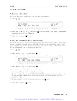
Page 64: ...nciators are ON To Trigger Internally 1 Press until the Int trigger annunciator 9 is ON To Trigger Manually 1 Press until the Man trigger annunciator 9 is ON 2 Press when you want to trigger a measurement To Trigger Externally 1 Connect the external trigger source to the EXT TRIGGER terminal on the 4338B s rear panel 2 Press until the Ext trigger annunciator 9 is ON 3 Apply a trigger signal to tri...

Page 65: ...e value Note When you want to set the limits only for the lower limit or the upper limit or the limits only for the primary parameter or the secondary parameter set the unnecessary parameter to OFF using the setting the minimum value or the setting the maximum value To start sorting 1 Press To display the sorting results Press The following menu is displayed Select Comprtr using or The display mod...

Page 66: ...value as the primary reference b Then the secondary parameter reference setting menu 1Ref Secondary is displayed Press to measure the secondary parameter and press to set the measurement value as the secondary reference To set by entering a value a Enter the primary parameter reference value using the numeric keys and press When you want to exit without changing value just press b Enter the second...

Page 67: ...d press Press or to select Off 1ABS or 1 and press 4 To select the secondary parameter deviation display mode press or to select Sec and press The same menu as the primary parameter is displayed and you can select the mode Off 1ABS or 1 in the same manner as the primary parameter Operating the 4338B 2 9 Artisan Technology Group Quality Instrumentation Guaranteed 888 88 SOURCE www artisantg com ...

Page 68: ...parator results Off turns the display OFF and press To exit from this menu select Exit and press If you select Digit the display digits selection menu appears Select the desired display digits using or and press After selecting the display digits the 4338B returns to the display mode selection menu 2 10 Operating the 4338B Artisan Technology Group Quality Instrumentation Guaranteed 888 88 SOURCE w...

Page 69: ...ide of the LCD display The information displayed and the order of display is as follows 1 Test signal level and Averaging rate 2 Trigger delay time and Source delay time 3 Comparator limits of the primary parameter 4 Comparator limits of the secondary parameter Operating the 4338B 2 11 Artisan Technology Group Quality Instrumentation Guaranteed 888 88 SOURCE www artisantg com ...

Page 70: ...To print the measurement data to an GPIB compatible printer without using an external controller 1 Set the printer to listen always mode 2 Connect the GPIB compatible printer to the 4338B s GPIB port 3 Turn the printer ON 4 Set the 4338B s GPIB address to 31 talk only mode Press The printer will begin printing the measurement data 5 When you want to stop printing change the 4338B s GPIB address to...

Page 71: ...t panel key s functionality For the handler interface test refer to Chapter 9 for the procedure The other tests are for use by service personnel only 1 Press 2 Select Svc using or and press 3 Select KEY using or and press 4 Press the front panel key that you want to test For example if you want to test then press When the key functions properly KEY CODE 5 TRIGGER is displayed otherwise there will ...

Page 72: ...t Check whether the Rmt annunciator is ON Check whether the external controller disables all the front panel controls by the LOCAL LOCKOUT command If so send the LOCAL command from the external controller Press Check whether the Key Lock annunciator is ON Check whether the handler or the 16064B LED display trigger box is connected to the 4338B and it locks out the keys If so unlock the keys from t...

Page 73: ...ction This chapter provides information on all of the 4338B s functions Front Panel Rear Panel Theory of Operation Function Reference 3 1 Artisan Technology Group Quality Instrumentation Guaranteed 888 88 SOURCE www artisantg com ...

Page 74: ...ternal Hold Range shows the measurement range mode Hold when the annunciator is displayed or Auto when the annunciator is not displayed Hold Level indicates that the 4338B is in the Hold level mode When in the Auto level mode the Hold level annunciator is not displayed Cmprtr On Comparator On indicates the comparator function is ON Cont Chk Contact Check On indicates the contact check function is ...

Page 75: ...to the instrument s chassis UNKNOWN Terminals These terminals are used to connect test xtures or test leads for measuring a DUT The connector type is BNC Caution DO NOT apply a dc voltage exceeding 6 42 V to UNKNOWN terminals or the 4338B s input circuits will be destroyed Auto Measurement Key The Auto Measurement key enables the Auto measurement function which allows the 4338B to measure a DUT au...

Page 76: ...at satis es the measurement limits for the selected test signal level The level key can also select the auto level mode In the auto level mode the test signal level is linked to the measurement range settings as follows Range 10 k 1 k 100 10 1 100 m 10 m 1 m Level 1 A 10 A 100 A 1 mA 10 mA When the auto level mode is not selected the Hold level annuunciator is displayed Note The 4338B s test signa...

Page 77: ...de displays the di erence between the measurement value and the nominal value as a percentage of the nominal value O turns OFF the deviation measurement mode default Measurement Time Key The Measurement Time key toggles the measurement time between Short Medium and Long The current setting is indicated by the Meas Time annunciator 9 While a Short measurement time setting gives the shortest measure...

Page 78: ...ey The Auto Hold range key toggles the measurement ranging mode between Auto and Hold The Auto mode selects the optimum measurement range automatically within 5 measurement cycles The Hold mode xes the measurement range setting to the range you select When the Hold mode is selected the Hold Range annunciator 9 will be displayed The default measurement range mode is Auto Range Setup Key The Range s...

Page 79: ... Bus mode GPIB only This mode is available only when in the GPIB remote state In the BUS trigger mode the GET and TRG commands will trigger a single shot measurement For more information refer to TRIGger Subsystem in Chapter 5 The mode selected is indicated by the Trigger annunciator 9 In the BUS mode the annunciator is not displayed Delay Key The Delay key sets the trigger delay time and the sour...

Page 80: ...parameter is none comp1 comparison result of primary parameter No output when the comparator function is OFF comp2 comparison result of secondary parameter No output when the comparator function is OFF Meaningless output when the secondary parameter is none 1 In 2 High 4 Low 8 no contact System reset or power on don t a ect the address setting Save Key The Save key stores the 4338B s current setti...

Page 81: ... Arrow Key and Right Up Arrow Key These keys serve the following functions While 4338B is displaying several items these keys are used to select a selected item blinks continuously adjacent items in the list selects the next item and the selects the previous item 0 1 9 0 minus point Key These keys are used to enter the numeric values of the 4338B s settings Enter Key The enter key terminates data ...

Page 82: ... comparator function ON and OFF The default comparator function is OFF The Comparator distinguishes whether or not the measurement result is within the upper and lower comparator limits for primary and secondary measurement parameter When the comparator function is ON the Comprtr On annunciator 9 will be displayed The comparison results output is assigned as follows Destination Condition Compariso...

Page 83: ...e jZsj is NOT less than 10 the 4338B displays WARNING Out Of Limit This is only a WARNING the SHORT correction data will still be used When the OVLD OVVOL or N C is displayed during the SHORT correction the 4338B will display WARNING Improper Correction When the contact check function is ON the values of 9 9999E13 are stored as R and X in the MeasVal At reset the correction data is cleared You can...

Page 84: ...beep whenever a system error or an operation error occurs In the beeper Off mode the error beep is turned OFF The setting is saved into EEPROM Line Available power line frequency selections are 50 Hz and 60 Hz The power line frequency setting is stored and does not change after reset or power o Once you set it you do not need to set the line frequency again as long as the power line frequency rema...

Page 85: ... A D converter display error message if fail1 16 8 Backup RAM display error message if fail2 32 1 During the power on test the 4338B suspends operation if an error occurs 2 During the power on test the 4338B uses its default setting and continues with the test The self test is also executed at power on After the test the 4338Bs settings are not a ected Exit return to measurement Function Reference...

Page 86: ... set to the External trigger mode the 4338B is triggered on the active low to high rising edge of a TTL level input pulse Figure 3 5 shows the speci cations required of the TTL pulse Figure 3 5 Required External Trigger Pulse Speci cation 3 14 Function Reference Artisan Technology Group Quality Instrumentation Guaranteed 888 88 SOURCE www artisantg com ...

Page 87: ...A type Time delay 0 5A 250V Agilent part number 2110 0202 230V 220 240Vac 610 UL CSA type Time delay 0 25A 250V Agilent part number 2110 0201 Serial Number Plate The serial number plate gives manufacturing information about the 4338B For details see Serial Number in Appendix A Power Cord Receptacle The Power Cord Receptacle is used to plug in the power cord Power Code The 4338B is equipped with a ...

Page 88: ...e Alarm Noti cation that a momentary power failure was detected Input Signal Opto isolated Keylock Front panel keyboard lockout External Trigger Pulse width 1 s Note The comparator output signals High In Low and the control signals INDEX EOM are available when the comparator function is ON And the contact check output signal N C is available when both the comparator and contact check functions are...

Page 89: ...result of primary parameter is IN 30 PLO Primary Parameter Low The comparison result of primary parameter is LOW 31 SHI Secondary parameter High The comparison result of secondary parameter is HIGH 32 SIN Secondary parameter In The comparison result of secondary parameter is IN 33 SLO Secondary parameter Low The comparison result of secondary parameter is LOW 38 OVVOL or Over Voltage The test volt...

Page 90: ...es of data between instruments and a controller With an GPIB system many di erent types of devices including instruments computers plotters and printers can be connected in parallel When con guring an GPIB system the following restrictions must be adhered to The length of cable between two devices must be less than or equal to four meters The total length of cable in one bus system must be less th...

Page 91: ...eceives device dependent data when addressed to listen In a GPIB system there can be any number of active listener at any given time Controller A controller manages the operation of the bus and addresses talker s and listener s In an GPIB system there can be only one active controller at any given time Table 3 3 lists the 4338B s GPIB capability and functions These functions provide the means for ...

Page 92: ...nce Figure 3 8 shows the Impedance de nition If the current through the DUT is I when test voltage V is applied across the DUT the DUT s impedance Z is expressed by Z V I Impedance Z contains a real and an imaginary part Figure 3 9 shows vector representation of impedance Figure 3 9 Vector Representation of Impedance 3 20 Function Reference Artisan Technology Group Quality Instrumentation Guarante...

Page 93: ...the result in the following measurement parameters R resistance X reactance L inductance Z jZj magnitude of impedance phase of impedance These parameters represent the DUT s electrical characteristics as Figure 3 10 Figure 3 10 Relationship between Measurement Parameters Function Reference 3 21 Artisan Technology Group Quality Instrumentation Guaranteed 888 88 SOURCE www artisantg com ...

Page 94: ... depends on the test voltage source level Vs the source resistance of the 4338B Rs and the impedance of the DUT RDUT as follows I V s Rs RDUT If the DUT s resistance is low enough to be assumed as 0 when compared with Rs the test current level I will be close to the selected level If DUT s resistance is high and cannot be assumed to be 0 when compared with Rs the test signal level will di er from ...

Page 95: ...ommands for Programmable Instruments SCPI programming or to discuss GPIB theory refer to the following documents which are better suited for these tasks For more information concerning BASIC refer to the manual set for the BASIC version being used BASIC Programming Techniques BASIC Language Reference For more information concerning SCPI refer to the following Beginner s Guide to SCPI For more info...

Page 96: ...he GPIB Address Before you can operate the 4338B in remote you need to know its GPIB address factory setting 17 To check the address press A typical display is The displayed response is the device address When sending a remote command you append this address to the GPIB interface s select code normally 7 For example if the select code is 7 and the device address is 17 the appended combination is 7...

Page 97: ...st commands Getting Data from the 4338B The 4338B can output readings and responses to query commands As an example have the 4338B generate a response to a query command by sending OUTPUT 717 IDN When you send a query from remote the 4338B does not display the response as it did when you executed the command from its front panel Instead the 4338B sends the response to its output bu er The output b...

Page 98: ...RIG SOUR command with the trigger source parameter When you select BUS as the trigger source sending TRG triggers a measurement and retrieves the measurement data 3 Retrieving the data The following sections describes how to perform the tasks at each step Figure 4 1 shows a simple capacitance measurement program Step 1 OUTPUT 717 RST Resetting OUTPUT 717 INIT CONT ON Initiating trigger system OUTP...

Page 99: ...g commands perform the SHORT correction SENS CORR COLL STAN2 SENS CORR For example to perform the SHORT correction OUTPUT 717 SENS CORR COLL STAN2 OUTPUT 717 OPC ENTER 717 A To Select the Measurement Parameter The following commands select the measurement parameter CALC1 FORM CALC2 FORM For example to select the R only mode OUTPUT 717 CALC1 FORM REAL OUTPUT 717 CALC2 FORM NONE For example to selec...

Page 100: ...uto range mode OUTPUT 717 SENS FIMP RANG AUTO ON For example to select the 1 range OUTPUT 717 SENS FIMP RANG AUTO OFF OUTPUT 717 SENS FIMP RANG 1 To Select the Test Signal Level The following commands select the test signal level SOUR CURR SOUR CURR AUTO For example to select the auto level mode OUTPUT 717 SOUR CURR AUTO ON For example to select 100 A OUTPUT 717 SOUR CURR AUTO OFF OUTPUT 717 SOUR ...

Page 101: ...TRIG SEQ2 DEL For example to set the trigger delay time to 10 ms OUTPUT 717 TRIG SEQ2 DEL 1E 2 For example to set the source delay time to 10 ms OUTPUT 717 TRIG DEL 1E 2 To Set the Beeper Mode The following commands set the beeper mode CALC 1 2 LIM BEEP CALC 1 2 LIM BEEP COND SYST BEEP SYST BEEP STAT For example to set the beeper mode to emit a beep when the comparison result is PASS OUTPUT 717 CA...

Page 102: ... EXPR CAT CALC 1 2 MATH STAT f1j2g shows that one of the two numbers is attached to the root mnemonic 1 means the primary parameter and 2 means the secondary parameter For example to set the reference values using the measured values and to calculate the absolute value of deviation for the primary parameter OUTPUT 717 FETC ENTER 717 s d1 d2 OUTPUT 717 DATA REF1 d1 OUTPUT 717 CALC1 MATH EXPR NAME D...

Page 103: ...ER 717 A PRINT A To Save and Recall Instrument Settings The following commands save and recall instrument settings SAV RCL To save the instrument settings to register no 1 OUTPUT 717 SAV 1 To recall the instrument settings from register no 1 OUTPUT 717 RCL 1 Remote Operation 4 9 Artisan Technology Group Quality Instrumentation Guaranteed 888 88 SOURCE www artisantg com ...

Page 104: ...p in the idle state use the INIT CONT command to turn ON the continuous activation of the trigger system 3 Trigger the instrument at your desired time An external controller can trigger the instrument with one of the following two commands Command Query response Applicable trigger mode TRG Yes The measured result is read out GPIB trigger TRIG No All 4 To repeat measurement repeat Step 3 Starting u...

Page 105: ...6 and Table 5 7 An SRQ service request is useful for detecting the completion of measurement in your program by using the information indicated by this register To detect the completion of measurement using SRQ use the following commands SRE STAT OPER ENAB The procedure is given below 1 Make the setup so that the 4338B generates an SRQ if bit 4 of the operation status event register is set to 1 2 ...

Page 106: ...d sets the trigger mode to the internal trigger Lines 80 to 90 Enables bit 4 of the operation status event register and enables bit 7 of the status byte register Lines 100 to 120 Clears the status byte register and operation status event register Lines 140 to 150 Sets the branch destination of the SRQ interrupt and enables the SRQ interrupt Lines 160 to 180 Starts up the trigger system once to sta...

Page 107: ... used to read out the measured data for each measurement Available trigger mode Readout procedure Using the TRG GPIB trigger Executing TRG command Bus Readout Triggering the instrument Using the FETC command All Executing FETC Readout When you want to read out the data of several measurements in batch use the data bu er Note The TRIGGER command of HT BASIC has the same function as the TRG command ...

Page 108: ...dress Line 70 Sets the data transfer format to the ASCII format Lines 90 to 100 Turns ON the trigger system continuous startup and sets the trigger mode to the GPIB trigger Lines 120 to 130 Reads out the ON OFF state of the comparator function and assigns it to the Comp ag variable Lines 170 to 210 After the trigger system state transitions to the trigger wait state triggers the instrument Line 23...

Page 109: ...easured Result Figure 4 4 Reading out the measured result in ASCII transfer format by using the TRG command Remote Operation 4 15 Artisan Technology Group Quality Instrumentation Guaranteed 888 88 SOURCE www artisantg com ...

Page 110: ... secondary parameter result and comparator sorting result Note Binary data must be read out without formatting Therefore use an I O path Binary set up for such readout This is also applicable to Line 290 Line 290 If the Comp ag value is not 1 the comparator function is OFF reads out the measurement status measured primary parameter result and measured secondary parameter result Line 310 Reads out ...

Page 111: ...t Measured Result Figure 4 5 Reading out the measured result in binary transfer format using TRG command Remote Operation 4 17 Artisan Technology Group Quality Instrumentation Guaranteed 888 88 SOURCE www artisantg com ...
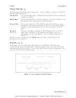
Page 112: ... 100 Turns ON the trigger system continuous startup and sets the trigger mode to the external trigger Lines 120 to 130 Reads out the ON OFF state of the comparator function and assigns it into the Comp ag variable Lines 170 to 210 Makes the setup generate an SRQ when measurement nishes and clears the status byte register and operation status event register Lines 250 to 260 Sets the branch destinat...

Page 113: ...Measured Result Figure 4 6 Reading out the measured result in ASCII transfer format using the FETC command Remote Operation 4 19 Artisan Technology Group Quality Instrumentation Guaranteed 888 88 SOURCE www artisantg com ...
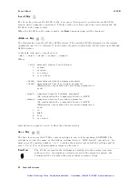
Page 114: ...s 310 to 340 Reads out the header part Line 360 If the Comp ag value is 1 the comparator function is ON reads out the measurement status measured primary parameter result measured secondary parameter result and comparator sorting result Note Binary data must be read out without formatting Therefore use an I O path Binary set up as such for readout This is also applicable to Line 380 Line 380 If th...

Page 115: ...ut Measured Result Figure 4 7 Reading out measured result in binary transfer format using FETC command Remote Operation 4 21 Artisan Technology Group Quality Instrumentation Guaranteed 888 88 SOURCE www artisantg com ...
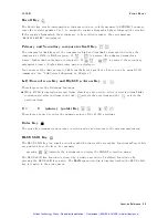
Page 116: ...al measurements and then later read out these results in batch The following commands use the data bu er function DATA DATA POIN DATA FEED DATA FEED CONT For example OPTION BASE 1 DIM D 600 OUTPUT 717 TRIG SOUR BUS OUTPUT 717 DATA POIN BUF1 200 OUTPUT 717 DATA FEED BUF1 CALC1 OUTPUT 717 DATA FEED CONT BUF1 ALW FOR I 1 TO 200 OUTPUT 717 TRIG NEXT I OUTPUT 717 DATA BUF1 ENTER 717 D PRINT D 4 22 Remo...

Page 117: ...UES COND STAT QUES ENAB STAT PRES HP BASIC SPOLL command For example to generate a service request whenever an error is placed in the error queue OUTPUT 717 ESE 52 SRE 32 For example to detect the completion of the actual measurement OUTPUT 717 SYST OPER ENAB 16 Enable Measuring bit OUTPUT 717 SRE 128 Enable Operation Status Register Summary bit REPEAT Wait until Operation Status Register Summary ...

Page 118: ...ere to branch to when interrupted ENABLE INTR 7 2 Enable an interrupt from GPIB interface LOOP END LOOP STOP Err_report Stat SPOLL 717 Clears the SRQ bit of the Status Byte OUTPUT 717 ESR Asks contents of the Standard Event Status Register ENTER 717 Estat PRINT Syntax Error detected OUTPUT 717 SYST ERR Asks to output error number and message ENTER 717 Err Err PRINT Err Err ENABLE INTR 7 RETURN END...

Page 119: ... problems are caused by an incorrect address and bad or loose GPIB cables If the 4338B Hangs Up When You Send ABORt Command Send the device clear command to the 4338B For example CLEAR 717 Remote Operation 4 25 Artisan Technology Group Quality Instrumentation Guaranteed 888 88 SOURCE www artisantg com ...

Page 120: ...Artisan Technology Group Quality Instrumentation Guaranteed 888 88 SOURCE www artisantg com ...

Page 121: ...e macros status registers synchronization and data storage All common commands begin with an asterisk Common commands are de ned in the IEEE 488 2 standard Common Commands CLS ESE numeric value ESE ESR IDN LRN OPC OPC OPT RCL numeric value RST SAV numeric value SRE numeric value SRE STB TRG TST WAI Subsystem Commands Subsystem commands include all measurement functions and some general purpose fun...

Page 122: ...only NAME fDEVjPCNTg STATe Boolean PATH query only DATA DATA fREF1jREF2g numeric value DATA fBUF1jBUF2g query only FEED fBUF1jBUF2g data handle CONTrol fBUF1jBUF2g fALWaysjNEVerg POINts fBUF1jBUF2g numeric value DISPlay WINDow STATe Boolean TEXT1 DIGit f3j4j5g PAGE f1j2g TEXT2 PAGE f1j2j3j4g FETCh query only FORMat DATA fASCiijREAL 64 g INITiate CONTinuous Boolean IMMediate no query SENSe AVERage ...

Page 123: ...ue UAjMA AUTO Boolean STATus OPERation CONDition query only ENABle numeric value EVENt query only PRESet no query QUEStionable CONDition query only ENABle numeric value EVENt query only SYSTem BEEPer IMMediate no query STATe Boolean ERRor query only KLOCk Boolean LFRequency numeric value PRESet VERSion query only TRIGger SEQuence1 DELay numeric value MSjS IMMediate no query SOURce fBUSjEXTernaljIN...

Page 124: ...hen the colon is the rst character of a command it speci es the following command mnemonic is a root level command Semicolon A semicolon separates two commands in the same message without changing the current path Common commands such as RST are not part of any subsystem The 4338B interprets them in the same way regardless of the current path setting Figure 5 1 shows examples of how to use the col...

Page 125: ...ce APERture Abbreviated mnemonics are also available for command headers In the above example FIMP APER is available Common Command Syntax Common commands do not have a hierarchical structure They are just sent as follows CLS Parameters There must be a space between the last command mnemonic and the rst parameter in a subsystem command FIMP APERtparameter t means a space ASCII character decimal 32...

Page 126: ...rogram message and query response sensor function and data handle are string parameters which contain ASCII characters A string must begin with a single quote ASCII 39 decimal or a double quote ASCII 34 decimal and end with the same character The quote to mark the beginning and end of the string is called the delimiter You can include the delimiter as part of the string by typing it twice without ...

Page 127: ...sage may contain both commas and semicolons as separators When a single query command returns multiple values a comma is used to separate each data item When multiple queries are sent in the same message the group of data items corresponding to each query are separated by a semicolon For example the ctitious query QUERY1 QUERY2 might return a response message of data1 data1 data2 data2 After the m...

Page 128: ...peci ed parameter is enabled Angular brackets enclose words or characters that are used to symbolize a program code parameter or an GPIB command Square brackets indicates that the enclosed items are optional f g When several items are enclosed by braces one and only one of these elements may be selected j A vertical bar is read as or and is used to separate alternative parameter options for exampl...

Page 129: ...ags to false for example ags that were set by the initiation of the trigger system See Trigger System Unlike RST ABORt does not alter the settings programmed by other commands No query Note After FETCh query TRG command or the BASIC command TRIGGER the ABORt command will cause the GPIB bus to hang up To avoid this before ABORt command execution clear the GPIB bus by executing the BASIC command CLE...

Page 130: ... subsystem is logically between the SENSe subsystem and data output to either the bus or the display and is used with the SENSe subsystem the DATA subsystem and FETCh query COMMAND PARAMETER CALCulatef1j2g FORMat fREALjMLINearjNONEjIMAGinaryjPHASejLSg LIMit BEEPer CONDition fFAIL j PASSg STATe Boolean CLEar FAIL LOWer DATA numeric value STATe Boolean STATe Boolean UPPer DATA numeric value STATe Bo...

Page 131: ...impedance PHASe phase of impedance LS equivalent series inductance NONE none Note You cannot set CALC1 FORM and CALC2 FORM to combinations not speci ed in Table 5 2 Table 5 2 Measurement Parameter Selection Parameters CALC1 FORM CALC2 FORM R REAL NONE R L REAL LS R X REAL IMAGinary Z 6 MLINear PHASe CALCulatef1j2g LIMit BEEPer CONDition f FAIL j PASS g De nes comparator output to the beeper CALCul...

Page 132: ... by CALCulate 1 2 LIMit FAIL command no query CALCulate1 selects the primary parameter CALCulate2 selects the secondary parameter CALCulatef1j2g LIMit FAIL Returns the comparison result of the selected parameter query only CALCulate1 selects the primary parameter CALCulate2 selects the secondary parameter Query response is 1 0 Where 1 comparison result is FAIL 0 comparison result is PASS CALCulate...

Page 133: ...alue of the selected parameter CALCulate1 selects the primary parameter CALCulate2 selects the secondary parameter numeric value is numeric 09 99921014 to 9 99921014 MAXimum 9 99921014 MINimum 09 99921014 CALCulatef1j2g LIMit UPPer STATe f ON j OFF j 1 j 0 g Sets or queries if the upper limit of the selected parameter is enabled CALCulate1 selects the primary parameter CALCulate2 selects the secon...

Page 134: ...te value of deviation PCNT percentage of deviation At RST CALCulate 1 2 MATH EXPRession NAME is set to DEV CALCulatef1j2g MATH STATe f ON j OFF j 1 j 0 g Sets or queries if math processing de ned by CALCulate 1 2 MATH EXPRession NAME is enabled ON 1 enables math processing OFF 0 disables math processing Query response is 1 0 CALCulatef1j2g PATH Returns the CALCulate subsystems in the order in whic...

Page 135: ...DATA DATA fREF1jREF2g numeric value DATA fBUF1jBUF2g FEED fBUF1jBUF2g data handle CONTrol fBUF1jBUF2g fALWaysjNEVerg POINts fBUF1jBUF2g numeric value DATA DATA f REF1 j REF2 g numeric value Enters the data into the data bu er REF1 or REF2 The 4338B has capability of deviation measurement which generates output of deviation between measurement result and user de ned nominal value The DATA DATA comm...

Page 136: ...s command Every data set contains the following data stat data comp Where stat measured status 0 normal 1 overload 2 no contact 4 over voltage data measured data comp comparison result 0 OFF 1 In 2 High 4 Low 8 no contact DATA FEED f BUF1 j BUF2 g data handle Sets or queries whether or not measurement data is fed into data bu er DATA FEED query requires the parameter BUF1 or BUF2 which is the name...

Page 137: ...y response is ALW NEV DATA POINts f BUF1 j BUF2 g numeric value Sets or queries the size of a data bu er The amount of measurement data that can be stored into the data bu er is de ned using this command This command returns data bu er pointer to the head of the bu er After that data will be stored from the head of the bu er DATA POINts query must have the parameter BUF1 or BUF2 which is the name ...

Page 138: ...gits 4 4 digits 5 5 digits Query response is 3 4 5 DISPlay WINDow TEXT1 PAGE f 1 j 2 g Sets or queries the display mode 1 displays the measurement results 2 displays the comparison results Query response is 1 2 DISPlay WINDow TEXT2 PAGE f1j2j3j4g Selects the mode of Measurement Settings Display 1 displays the test signal level and averaging rate 2 displays the trigger delay and source delay 3 disp...

Page 139: ...r Meaningless output when the secondary parameter is none comp1 comparison result of the primary parameter No output when comparator is OFF 1 In 2 High 4 Low 8 no contact comp2 comparison result of the secondary parameter No output when comparator is OFF Meaningless output when the secondary parameter is none 1 In 2 High 4 Low 8 no contact Data format is speci ed using the FORMat subsystem For mor...

Page 140: ... the DATA subsystem or the FETCh query ASCii sets the data transfer format to the ASCII transfer format REAL 64 sets the data transfer format to the real 64 bit transfer format For details about the data transfer formats see Data Transfer Format Query response is ASC REAL 64 5 20 GPIB Reference Artisan Technology Group Quality Instrumentation Guaranteed 888 88 SOURCE www artisantg com ...

Page 141: ...uses the trigger system to initiate and complete one full trigger cycle returning to IDLE on completion If the 4338B is not in IDLE or if INITiate CONTinuous is set to ON an INITiate IMMediate command has no e ect on the trigger system and error 0213 is generated No query INITiate CONTinuous f ON j OFF j 1 j 0 g The INITiate CONTinuous command sets or queries whether or not the trigger system is b...

Page 142: ...Se AVERage STATe f ON j OFF j 1 j 0 g Sets or queries if averaging is enabled ON 1 enables averaging OFF 0 disables averaging Query response is 1 0 SENSe CORRection COLLect ACQuire STANdard2 Performs a SHORT correction The instrument takes SHORT correction data which cancels measurement errors due to the residual impedance of the cable and test xture no query The SHORT correction must be performed...

Page 143: ...ted The short form must be STAN2 SENSe CORRection STATe f ON j OFF j 1 j 0 g Sets or queries if the SHORT correction data taken by SENSe CORRection COLLect ACQuire STANdard2 is enabled ON 1 enables the SHORT correction data OFF 0 disables the SHORT correction data Query response is f1j0g Note The SHORT correction can be set to ON or OFF only by using GPIB commands and cannot be set by using front ...

Page 144: ...ment range Available measurement ranges are 1 m 10 m 100 m 1 10 100 1 k and 10 k which are limited by the test level setting See Figure 3 2 numeric value is numeric 1 0210 3 1 0210 2 1 0210 1 1 0 1 0210 1 02102 1 02103 1 02104 MAXimum 10 k MINimum 1 m UP move to upper range DOWN move to lower range Following su xes can be used with numeric value MOHM m OHM KOHM k SENSe FUNCtion sensor function Set...

Page 145: ...mum 10 mArms MINimum 1 Arms The following su xes can be used with numeric value UA A MA mA Query response is numeric value Note The peak voltage across the DUT must be always less than 20 mV When the peak voltage across the DUT exceeds 20 mV the source output level is reduced to 0 V and the 4338B displays OVVOL Over Voltage For details see Dry Circuit Loop in Chapter 7 SOURce CURRent LEVel IMMedia...

Page 146: ...ructive read STATus OPERation CONDition Returns the contents of the condition register of the standard operation status group Query only Query response is a decimal expression of the contents of the register in NR1 format Note Reading the condition register is nondestructive the contents of the register are still contained in the register after the register is read STATus OPERation ENABle numeric ...

Page 147: ...Returns the contents of the condition register of the standard questionable status group Query only Query response is a decimal expression of the contents of the register in NR1 format The 4338B has no operation to report the event to the questionable status condition register all of whose bits are always set to 0 STATus QUEStionable ENABle numeric value Sets or queries the enable register of the ...

Page 148: ...d OFF 0 disables the all beeper including the error beep Query response is 1 0 SYSTem ERRor Returns the existing error numbers and messages in the 4338B s error queue Query only SYSTem KLOCk f ON j OFF j 1 j 0 g Sets or queries whether or not the front panel keys of the 4338B are locked ON 1 the front panel keys are locked OFF 0 the front panel keys are unlocked Query response is 1 0 SYSTem LFRequ...

Page 149: ...ium Averaging 1 Trigger mode Internal Trigger delay 0 ms Comparator OFF Display mode Measured data Beep FAIL beep mode Data transfer format ASCII SYSTem VERSion Returns the value corresponding to SCPI version number for which the 4338B complies Query only Query response is YYYY V in NR2 format Where YYYY year version V revision number for the year GPIB Reference 5 29 Artisan Technology Group Quali...

Page 150: ...f BUS j EXTernal j INTernal j MANual g Sets or queries the trigger mode BUS GET command and TRG command triggers a single short measurement EXTernal TTL pulse input through the rear panel external trigger connector or through the handler interface triggers a measurement INTernal makes free running continuous measurements MANual The 4338B performs a measurement in response to the front panel trigge...

Page 151: ...the register in NR1 format 3IDN The 3IDN identi cation query returns an identi cation string which consist of 4 elds separated by commas Query response is Field 1 Field 2 Field 3 Field 4 Where Field 1 manufacturer always HEWLETT PACKARD Field 2 model number always 4338A Field 3 serial number in HP format like 2419J00100 Field 4 rmware version number like 01 00 3LRN The 3LRN learn Device Setup quer...

Page 152: ...e CONTinuous OFF SENSe CORRection STATe OFF SYSTem KLOCk OFF 3SAV numeric value The 3SAV save command saves the instrument state in the speci ed register The 4338B has 10 available storage registers 0 through 9 numeric value is numeric 0 to 9 NR1 format 3SRE numeric value The 3SRE service request enable command sets the bits of the service request enable register numeric value is numeric decimal e...

Page 153: ...xecutes an internal self test and returns the test result as the sum of all existing errors codes If there are no error the 4338B returns 0 Test Item Error Code 1 RAM read write 1 2 EPROM 2 3 Calibration data EEPROM 4 4 User s data EEPROM 8 5 AD converter 16 6 Backup RAM 32 Query response is 0 to 63 in NR1 format 3WAI The 3WAI the wait to continue command makes the 4338B wait until all previously ...

Page 154: ...RQ Service Request control signal when it requires the controller to perform a task When the 4338B generates an SRQ it also sets Bit 6 of the status byte RQS Request Service bit Service Request Enable Register allows an application programmer to select which summary messages in the status byte register may cause service requests Illustrated in Figure 5 3 5 34 GPIB Reference Artisan Technology Grou...

Page 155: ...set to 0 Table 5 3 Status Byte Assignments Bit No Bit Weight Description 7 128 Operation Status Register Summary Bit 6 64 Request Service Bit This bit is set when the any enabled bit of the status byte has been set which indicates 4338B has at least one reason for requesting service SPOLL resets this bit 5 32 Standard Event Status Register Summary Bit 4 16 MAV Message Available Bit This bit is set...

Page 156: ...ors occur An IEEE 488 2 syntax error occurred The 4338B received a Group Execute Trigger get inside a program message 4 16 Execution Error Bit This bit is set when a parameter of a GPIB command was outside of its legal input range or is otherwise inconsistent with the 4338B s capabilities 3 8 Device Dependent Error Bit This bit is set when so many errors have been occurred that the error queue is ...

Page 157: ... an event register and an enable resister Illustrated in Figure 5 5 The condition register re ects the internal states of 4338B So each time the 4338B s condition is changed its condition bit is changed from 0 to 1 or from 1 to 0 The event register s bits correspond to the bits in the condition register The transition lter reports to the event register that an event a bit changed from 1 to 0 has t...

Page 158: ...Weight Description 10 15 Always 0 zero 9 512 This bit is set when the BUF2 has become full 8 256 This bit is set when the BUF1 has become full 7 128 This bit is set when the correction data measurement has completed 6 Always 0 zero 5 32 This bit is set when the 4338B has become able to accept a trigger 4 16 This bit is set when the measurement has completed 3 Always 0 zero 2 4 This bit is set when...

Page 159: ... delay time between measurements Figure 5 6 Trigger System Con guration Figure 5 6 shows the logical con guration of the 4338B s trigger system Each undashed block is called a trigger state The 4338B moves between adjacent trigger states depending on its condition The power ON state is called the idle state You can force the 4338B to the idle state using the ABORt or RST commands The initiate and ...

Page 160: ... additional quali cations may apply DELay The TRIGger DELay command allows you to specify a time delay after the trigger signal is detected to the start of the measurement For example you may want to delay acquiring data until 5 milliseconds after the positive edge to allow the measurement signal to settle For example using a delay time allows relay contacts to stop bouncing before making a measur...

Page 161: ...at as appropriate The numbers are separated by commas as speci ed in the IEEE 488 2 standard Figure 5 8 NR1 Format Figure 5 9 NR2 Format Figure 5 10 NR3 Format For example expression of 1000 are 1000 NR1 format 1000 0 NR2 format 1 0E3 NR3 format GPIB Reference 5 41 Artisan Technology Group Quality Instrumentation Guaranteed 888 88 SOURCE www artisantg com ...

Page 162: ...s the same data format used by the HP Technical computers such as the HP 9000 series 200 300 computers The real number RN represented in oating point format are provided by following formula When 0 e 11111111111 2047 RN 01 S 2 2 EXP 1023 2 1 f 252 When e 0 RN 01 S 2 2 1022 2 f 252 When e 0 f 0 RN 0 Where s value of the sign part binary e value of the exponential part binary EXP decimal expression ...

Page 163: ...escribes typical measurement applications Measuring Contact Resistance of Relays or Switches Measuring Internal Resistance of Batteries Application Measurement 6 1 Artisan Technology Group Quality Instrumentation Guaranteed 888 88 SOURCE www artisantg com ...

Page 164: ...mode Press to display the mesurement parametor menu Press or until R is blinking and press 3 Activate the Auto Measurement mode Press when the auto measurement indicator is OFF The Auto Measurement function allows the 4338B to measure a DUT automatically using the optimum measurement range and the test signal level 4 Perform the SHORT compensation a Connect the 16005B Kelvin clip leads to each oth...

Page 165: ... Resistance of Relays or Switches b Press c Press or until ShortMeas is blinking and press 5 Connect DUT Application Measurement 6 3 Artisan Technology Group Quality Instrumentation Guaranteed 888 88 SOURCE www artisantg com ...

Page 166: ...or Switches 4338B Figure 6 1 Measuring Contact Resistance The following gure shows the typical measurement result display 6 4 Application Measurement Artisan Technology Group Quality Instrumentation Guaranteed 888 88 SOURCE www artisantg com ...

Page 167: ...es using a handler 1 The following gure is the typical measurement system using a handler Refer to Extending Test Leads in Chapter 7 for the information on how to extend the test leads Figure 6 2 Measuring Internal Resistance of Batteries Application Measurement 6 5 Artisan Technology Group Quality Instrumentation Guaranteed 888 88 SOURCE www artisantg com ...

Page 168: ...hen press Continue 230 PAUSE 240 DISP 250 260 OUTPUT Hp4338 CALC1 LIM LOW MIN UPP 0 01 270 OUTPUT Hp4338 CALC1 LIM STAT ON 280 OUTPUT Hp4338 DISP OFF 290 OUTPUT Hp4338 TRIG SOUR EXT 300 OUTPUT Hp4338 FORM REAL 310 320 OUTPUT Hp4338 DATA POIN BUF1 200 330 OUTPUT Hp4338 DATA FEED BUF1 CALC1 340 OUTPUT Hp4338 DATA FEED CONT BUF1 ALW 350 360 OUTPUT Hp4338 STAT OPER ENAB DVAL 0000000100000000 2 370 OUT...

Page 169: ...nsfer format Lines 320 to 340 Set the size of the data bu er BUF1 to 200 set to feed the R measurement data which was speci ed by CALC1 FORM command and feed data into the data bu er whenever the new data available Lines 360 and 370 Enables the BUF1 full bit of the operation status register and the operation status register summary bit of the status byte register Line 380 Sets the trigger system a...

Page 170: ...Artisan Technology Group Quality Instrumentation Guaranteed 888 88 SOURCE www artisantg com ...

Page 171: ... SHORT Correction The SHORT correction function reduces the measurement error due to the residual impedance existing between the 4338B s UNKNOWN terminals and the DUT Figure 7 1 SHORT Correction Measurement Basics 7 1 Artisan Technology Group Quality Instrumentation Guaranteed 888 88 SOURCE www artisantg com ...

Page 172: ...le value of measurement range being used the measurement accuracy will be reduced This sometimes cause a discontinuity occurs in the measurement values at the measurement range boundaries If measurement range is set to Auto range the impedance curve will skip when impedance range change occurs To prevent this from occurring the impedance range should be set to the Hold range mode Dry Circuit Loop ...

Page 173: ...ture use the connection methods shown in Figure 7 2 The names in the parenthesis are the terminals on the 4338B s front panel The LCUR terminal is not used for measurement Figure 7 2 Test Lead Extension Measurement Basics 7 3 Artisan Technology Group Quality Instrumentation Guaranteed 888 88 SOURCE www artisantg com ...

Page 174: ...Artisan Technology Group Quality Instrumentation Guaranteed 888 88 SOURCE www artisantg com ...

Page 175: ...is chapter provides the following general information for the 4338B Speci cations Supplemental Performance Characteristics General Information 8 1 Artisan Technology Group Quality Instrumentation Guaranteed 888 88 SOURCE www artisantg com ...

Page 176: ... Time Mode Short Medium and Long Ranging Auto and Hold manual Averaging 1 to 256 Trigger Mode Internal Manual External and Bus Trigger Delay Time 0 to 9 999 seconds in 0 001 seconds steps Source Delay Time 0 to 9 999 seconds in 0 001 seconds steps Test Cable Length 2 meters maximum Measurement Range Parameter Measurement Range Contact Check R 10 to 100 k O 10 to 10 k On 8 2 General Information Art...

Page 177: ... performed Accuracy applies when X R 2 Multiply the accuracy by the following temperature induced error factors 18 C T 28 C 2 1 8 C T 18 C or 28 C T 38 C 2 2 0 C T 8 C or 38 C T 45 C 2 4 Where T is the temperature General Information 8 3 Artisan Technology Group Quality Instrumentation Guaranteed 888 88 SOURCE www artisantg com ...

Page 178: ... 0 4 2 501 Rm Rm 2000 0 85 50 001 Rm 0 4 6 001 Rm 0 4 1 501 Rm 0 85 10 001 Rm 0 4 1 501 Rm 0 4 0 401 Rm 0 85 1 701 Rm 0 4 0 501 Rm 0 4 0 131 Rm 0 85 3 501 Rm 0 4 1 001 Rm 0 4 0 251 Rm 0 85 5 001 Rm 0 4 0 601 Rm 0 4 0 151 Rm 0 85 1 001 Rm 0 4 0 151 Rm 0 4 0 041 Rm 0 85 0 171 Rm 0 4 0 051 Rm 0 4 0 014 Rm 0 85 0 351 Rm 0 4 0 101 Rm 0 4 0 026 Rm 0 85 0 501 Rm 0 4 0 061 Rm 0 4 0 016 Rm 0 85 0 101 Rm 0 ...

Page 179: ...mposed DC Up to 642 V can be present on the measurement terminals Save Recall Ten instrument setups can be saved and recalled from the internal non volatile memory Continuous Memory Capability If the instrument is turned OFF or if a power failure occurs the instrument settings are automatically saved Key Lock Disables key input from the front panel GPIB Interface All control settings measurement v...

Page 180: ...EN 61000 3 3 1995 IEC 1000 3 3 1994 Complies with EN 50082 1 1992 IEC 801 2 1991 4 kV CD 8 kV AD Complies with EN 50082 1 1992 IEC 801 3 1984 3 V m Complies with EN 50082 1 1992 IEC 801 4 1988 0 5 kV Signal Lines 1 kV Power Lines This ISM device complies with Canadian ICES 001 Cet appareil ISM est conforme a la norme NMB 001 du Canada Dimensions approximately 320 W by 100 H by 300 D mm Weight appr...

Page 181: ... 10 H 6 0180 to 180 Measurement Range when Contact Check is ON Parameter Measurement Range X jZj 10 to 10 k L 10 to 1 H 6 0180 to 180 Continuous Memory Duration 72 hours 2365 C Measurement Time The following table shows typical measurement times Mode Analog Measurement Digital Computation Total1 Short 27 7 34 Medium 63 7 70 Long 890 10 900 1 Time interval from a trigger command to EOM end of measu...

Page 182: ...tal Computation Total1 Short 432 ms 112 ms 544 ms Medium 1008 ms 112 ms 1120 ms Long 14240 ms 160 ms 14400 ms 1 Time interval from a trigger command to EOM end of measurement signal output at the handler interface port ranging hold display mode o 8 8 General Information Artisan Technology Group Quality Instrumentation Guaranteed 888 88 SOURCE www artisantg com ...

Page 183: ...stitute 42032A2 1 P 100 m Standard Resistor No Substitute 42033A2 1 P 1 Standard Resistor No Substitute 42034A2 1 P 10 Standard Resistor No Substitute 42035A2 1 P 100 Standard Resistor No Substitute 42036A2 16074A 1 P 1 k Standard Resistor No Substitute 42037A2 16074A 1 P 10 k Standard Resistor No Substitute 42038A2 16074A 1 P SHORT Termination No Substitute 42091A 16074A 1 P Adapter Dual Banana B...

Page 184: ...en performance testing the 4338B Equipment which equals or surpasses the key required speci cations of the recommended equipment may be used as a substitute Calculation Sheet The calculation sheet is used as an aid for recording raw measurement data and for calculating the performance test results The performance test procedure gives the test sequence for performing a test the complete set of meas...

Page 185: ...during incoming inspection can be used for comparison purposes during periodic maintenance troubleshooting and after repair or adjustment Calibration Cycle The 4338B requires periodic performance tests The frequency of performance testing depends on the operating and environmental conditions under which the 4338B is used Verify the 4338B s performance at least once a year using the performance tes...

Page 186: ...120 1839 Procedure 1 Reset the 4338B using the following procedure a Press to display the system reset menu b Press or until Yes blinks and press 2 Set up the equipment as shown in Figure 9 1 Figure 9 1 Test Signal Frequency Accuracy Test Setup 3 Set the test signal level to 10 mA using the following procedure a Press to display the test signal level setting menu b Press or until 10 mA blinks and ...

Page 187: ...Counter Reading line Note The counter may display strange frequency readings for a moment in this test this is because the 4338B turns the test signal o after each measurement The delay time in which the 4338B outputs the test signal continuously is used to ease the test signal frequency measurement 6 Calculate the test result according to the calculation sheet and record the result into the perfo...

Page 188: ...stor 42033A1 1 Standard Resistor 42034A1 10 Standard Resistor 42035A1 100 Standard Resistor 42036A12 1 k Standard Resistor 42037A12 10 k Standard Resistor 42038A12 SHORT Termination 42091A2 1 Part of 42030A Standard Resistor Set 2 16074A can be used as a substitute Procedure 1 Record the 42030A Standard Resistor Set s calibration values on the calculation sheet 2 Reset the 4338B using the followin...

Page 189: ... Resistor to the 4338B s UNKNOWN terminals 8 Set the test signal level to 10 mA using the following procedure a Press to display the test signal level setting menu b Press or until 10 mA blinks and press 9 Press to measure 10 Record the 4338B reading of R on the calculation sheet 11 Calculate the test result according to the calculation sheet and record the result into the performance test record ...

Page 190: ...e Measurement Accuracy Test Settings Standard Test Signal Level 1 m 10 mA 10 m 10 mA 100 m 1 mA 1 10 mA 10 10 A 100 1 A 1 k 10 A 10 k 1 A 9 8 Maintenance Artisan Technology Group Quality Instrumentation Guaranteed 888 88 SOURCE www artisantg com ...

Page 191: ...t Accuracy Test Standard Test Signal Current Standard Calibration Value a 4338B Reading b Test Result Equation 1 m 10 mA m m b 0 a 10 m 10 mA m m b 0 a 100 m 1 mA m m b 0 a 1 10 mA b 0 a 10 10 A b 0 a 100 1 A b 0 a 1 k 10 A k k b 0 a 10 k 1 A k k b 0 a Maintenance 9 9 Artisan Technology Group Quality Instrumentation Guaranteed 888 88 SOURCE www artisantg com ...

Page 192: ...1 kHz Resistance Measurement Accuracy Test Standard Test Signal Current Test Limits Test Result1 Measurement Uncertainty 1 m 10 mA 60 024 m m 60 001 m 10 m 10 mA 60 054 m m 60 010 m 100 m 1 mA 60 45 m m 60 10 m 1 10 mA 60 0043 60 0010 10 10 A 60 044 60 003 100 1 A 60 49 60 021 1 k 10 A 60 0093 k k 60 00021 k 10 k 1 A 60 54 k k 60 0021 k 1 Test Result Measured Value 0 Standard s Calibration Value 9...

Page 193: ...ed to be performed during the 4338B performance testing Record the test signal level functional test result in the test record at the end of this section Test Equipment Table 9 1 lists the test equipment required to perform the tests described in this section Equipment which equals or surpasses the key required speci cations of the recommended equipment may be used Maintenance 9 11 Artisan Technol...

Page 194: ...es blinks and press 2 Set up the equipment as shown in Figure 9 3 Figure 9 3 Test Signal Level Functional Test Setup 3 Set the 3458A Multimeter to Synchronously Sub sample AC voltage measurement mode using the following procedure a Press 4ACV5 to set the measurement mode to AC voltage b Press 4Shift5 4S5 495 495 495 to display SETACV c Press 475 495 495 495 to display SYNC then press 4Enter5 4 Set...

Page 195: ...isted in Table 9 3 Note The multimeter may display strange voltage readings for a moment in this test this is because the 4338B turns the test signal o after each measurement The delay time in which the 4338B outputs the test signal continuously is used to ease the test signal level measurement 7 Perform this test for all settings listed in Table 9 3 Table 9 3 Test Signal Level Minimum Limit Maxim...

Page 196: ...r Interface Functional Test Setup 4 Turn the 4338B ON 5 Reset the 4338B using the following procedure a Press to display the system reset menu b Press or until Yes blinks and press Key Lock Function Test 6 Set the IN4 switch on the Handler Interface Tester to 1 7 Con rm that the all keys on the 4338B s front panel are locked out 8 Set the IN4 switch on the Handler Interface Tester to 0 External Tr...

Page 197: ...t the LED PW switch to ON except when doing the handler interface output test The LEDs may cause the 4338B to shut down during normal operation 13 Con rm that the LEDs on the Handler Interface Tester light in the order shown in Figure 9 5 in accordance with the 4338B display Figure 9 5 Handler interface Output Order 14 Set the LED PW switch on the Handler Interface Tester to OFF 15 Press twice to ...

Page 198: ...d Agilent 4338B Milliohmmeter Test Signal Level Functional Test Serial No Date Temperature Tested by Humidity Pass Fail 9 16 Maintenance Artisan Technology Group Quality Instrumentation Guaranteed 888 88 SOURCE www artisantg com ...

Page 199: ...umber or ROM version is not listed on the title page of this manual in Table A 1 or Table A 2 make changes according to the yellow MANUAL CHANGES supplement In additions to information on changes the supplement may contain information for correcting errors Errata in the manual To keep this manual as current and accurate as possible Agilent Technologies recommends that you periodically request the ...

Page 200: ...C is displayed during the SHORT correction the 4338B will display WARNING Out Of Limit The SHORT correction data will still be used A 2 Manual Changes Artisan Technology Group Quality Instrumentation Guaranteed 888 88 SOURCE www artisantg com ...

Page 201: ...tamped on the serial number plate see Figure A 1 attached to the rear panel The rst ve characters are the serial pre x and the last ve digits are the su x Figure A 1 Serial Number Plate Manual Changes A 3 Artisan Technology Group Quality Instrumentation Guaranteed 888 88 SOURCE www artisantg com ...

Page 202: ...Artisan Technology Group Quality Instrumentation Guaranteed 888 88 SOURCE www artisantg com ...

Page 203: ...its of the dc isolated outputs are divided into two types See Table B 1 A simpli ed diagram of the output signals is shown in Figure B 1 for comparison signals and Figure B 2 for control signals Table B 1 Handler Output Electrical Characteristics Output Signals Voltage Output Rating Maximum Current External Voltage Circuit Common Low High Comparison Signals PHI PIN PLO SHI SIN SLO OVVOL or N C 0 5...

Page 204: ... Characteristics 4338B Figure B 1 Handler Interface Comparison Output Signals Diagram B 2 Handler Interface Installation Artisan Technology Group Quality Instrumentation Guaranteed 888 88 SOURCE www artisantg com ...

Page 205: ...ctrical Characteristics Figure B 2 Handler Interface Control Output Signals Diagram Handler Interface Installation B 3 Artisan Technology Group Quality Instrumentation Guaranteed 888 88 SOURCE www artisantg com ...

Page 206: ...rd The electrical characteristics of the signals are listed in Table B 2 A diagram for the input signals is shown in Figure B 3 Table B 2 Handler Input Electrical Characteristics Signal Input Voltage Input Current Low Pull up Voltage Circuit Common Low High 5 V 12 V 15 V EXT TRIG 1 V 5 to 15 V 8 7 mA 10 5 mA 13 5 mA COM2 KEY LOCK 1 V 5 to 15 V 7 7 mA 10 8 mA 13 6 mA COM2 Figure B 3 Handler Interfa...

Page 207: ...em use only Pozidrive screwdrivers to remove or tighten Pozidrive type fasteners Procedure 1 Disconnect the power cable from the 4338B and allow enough time 10 minutes for the internal capacitors to discharge Warning Dangerous energy and voltage levels exist within the 4338B when it is in operation and just after it is powered down Allow 10 minutes for the 4338B s internal capacitors to discharge ...

Page 208: ...onnect the A2 assembly to the A1 main board on the bottom d Remove the A2 board from the chassis 5 Remove the A1 main board assembly a Disconnect the following cable assemblies from the A1 board i Four cables which are connected to the UNKNOWN connectors on the Front Panel ii The cable assembly from the transformer iii Two cable assemblies from the dc dc converter B 6 Handler Interface Installatio...

Page 209: ...the chassis d Remove the A1 board from the chassis Figure B 4 shows the location of the socket for the pull up resisters J5 and the switch for EXT DCV2 voltage setting SW1 Table B 3 lists the location of the pull up resisters Figure B 4 A1 Main Board Location Handler Interface Installation B 7 Artisan Technology Group Quality Instrumentation Guaranteed 888 88 SOURCE www artisantg com ...

Page 210: ...g equation to determine the value of the pull up resistors R R k Vp V 3 where Vp is the pull up voltage The typical pull up resistor values are Pull up Voltage Pull up Resistor Agilent Part Number 5 V 0757 0278 1 78 k 12 V 0757 0279 3 16 k 24 V 0757 0441 8 25 k 7 Mount the pull up resistors for the control output signals Refer to Figure B 4 and Table B 3 for the location of the pull up resistors f...

Page 211: ...8 5 11 k 8 Set the SW1 according to the voltage value of EXT DCV2 EXT DCV2 EXT TRIG KEY LOCK SW1 1 SW1 2 SW1 3 5 to 6 V Close Close Close 6 to 9 V Close Open Close 9 to 15 V Open Close Open 9 Reinstall the A1 main board the A2 CPU board and the cover Handler Interface Installation B 9 Artisan Technology Group Quality Instrumentation Guaranteed 888 88 SOURCE www artisantg com ...

Page 212: ...Artisan Technology Group Quality Instrumentation Guaranteed 888 88 SOURCE www artisantg com ...

Page 213: ...e signal level N C No Contact N C N C OVVOL or N C State 2 2 Data 9 9999E13 Comp 3 8 Cancel the bad contact between the DUT and the contact pin 1 Refer to the FETCh Command in Chapter 5 2 Measurement Status 0 Normal 1 Overload 2 No Contact 4 Over Voltage 3 Comparison result 1 IN 2 HIGH 4 LOW 8 No Contact 4 OVVOL signal or N C signal is detected from the Pin No 38 in the 4338B Handler Interface Cau...

Page 214: ... range Change to the appropriate signal level N C OVVOL N C N C OVVOL or N C State 2 2 Data 9 9999E13 Comp 3 8 Change to the appropriate signal level Cancel the bad contact between the DUT and the contact pin OVVOL High PHI and SHI and OVVOL or N C State 2 4 Data 9 9999E13 Comp 3 2 1 Refer to the FETCh Command in Chapter 5 2 Measurement Status 0 Normal 1 Overload 2 No Contact 4 Over Voltage 3 Comp...

Page 215: ...signal level Cancel the bad contact between the DUT and the contact pin OVVOL High PHI and SHI or OVVOL or N C State 2 4 Data 9 9999E13 Comp 3 2 1 Refer to the FETCh Command in Chapter 5 2 Measurement Status 0 Normal 1 Overload 2 No Contact 4 Over Voltage 3 Comparison result 1 IN 2 HIGH 4 LOW 8 No Contact 4 OVVOL signal or N C signal is detected from the Pin No 38 in the 4338B Handler Interface Ca...

Page 216: ...Artisan Technology Group Quality Instrumentation Guaranteed 888 88 SOURCE www artisantg com ...

Page 217: ...ts the error messages that are displayed on the 4338B s LCD display or transmitted by the instrument over GPIB in numerical order Messages 1 Artisan Technology Group Quality Instrumentation Guaranteed 888 88 SOURCE www artisantg com ...

Page 218: ...ings in backup memory for 72 hours after being turned OFF 17 SAVE FAILED Contact your nearest Agilent Technologies o ce 18 RECALL FAILED No instrument setting saved in the EEPROM 19 PRINTER NO RESPONSE Something is wrong check the following items Check that the power code is connected to your printer Check that the GPIB cable is connected between the printer and the instrument Check that the print...

Page 219: ...as expected but block data was encountered 105 GET not allowed A Group Execute Trigger GET was received within a program message see IEEE 488 2 7 7 108 Parameter not allowed More parameters were received than expected for the header for example the SENSe AVERage COUNt command only accepts one parameter so receiving AVER COUN 2 4 is not allowed 109 Missing parameter Fewer parameters were received t...

Page 220: ...t a more speci c error 141 Invalid character data Either the character data element contains an invalid character or the particular element received is not valid for the header 144 Character data too long The character data element contains more than twelve characters see IEEE 488 2 7 7 1 4 148 Character data not allowed A legal character data element was encountered that s prohibited by the 4338B...

Page 221: ...egal character 178 Expression data not allowed A legal expression data was encountered but was not allowed by the 4338B at this point in the syntax analysis process 200 Execution errors This is the generic syntax error that the 4338B cannot detect more speci c errors This code indicates only that an execution error as de ned in IEEE 488 2 11 5 1 1 5 has occurred 211 Trigger ignored A GET TRG or tr...

Page 222: ...ntered into the queue in lieu of the code that caused the error This code indicates that there is no room in the queue and an error occurred but was not recorded 400 Query errors This is the generic query error that the 4338B cannot detect more speci c errors This code indicates only that a query error as de ned in IEEE 488 2 11 5 1 1 7 and 6 3 has occurred 410 Query INTERRUPTED A condition causin...

Page 223: ...ulate 1 2 LIMit LOWer DATA 4 8 5 12 CALCulate 1 2 LIMit LOWer STATe 4 8 5 13 CALCulate 1 2 LIMit STATe 4 8 5 13 CALCulate 1 2 LIMit UPPer DATA 4 8 5 13 CALCulate 1 2 LIMit UPPer STATe 4 8 5 13 CALCulate 1 2 MATH EXPRession 4 8 5 13 5 14 CALCulate 1 2 MATH STATe 4 8 5 14 CALCulate subsystem 5 10 calculation sheet 9 9 cleaning 1 9 CLEar CALCulate 1 2 LIMit 5 12 CLS 4 23 5 31 Command Error CME Bit 5 ...

Page 224: ...ture SENSe 5 23 FIMPedance CONTact VERify SENSe 5 24 FIMPedance RANGe UPPer SENSe 5 24 FORMat 5 20 CALCulate 1 2 5 11 FORMat subsystem 5 20 FUNCtion SENSe 5 24 functional test record 9 16 G GET 4 10 GPIB address 3 8 how to set 2 12 group execution trigger 4 10 H handler interface installation B 1 handler interface functional test 9 14 I idle state 5 39 IDN 5 31 IEEE 754 oating point format 5 42 IM...

Page 225: ...TATus 5 27 SYSTem 5 29 Pri key 3 9 Q Query Error Bit 5 36 QUEStionable STATus 5 27 QUEStionable CONDition STATus 5 27 QUEStionable ENABle STATus 5 27 questionable status register 5 38 R Range Setup key 3 6 RCL 4 9 5 32 Rcl key 3 9 real data format 5 20 5 42 recall 3 9 GPIB command 5 32 instrument settings 2 4 REF1 5 15 REF2 5 15 reset 3 12 GPIB command 5 29 how to 1 20 4 5 resistance measurement a...

Page 226: ...7 SYSTem BEEPer IMMediate 4 7 5 28 SYSTem BEEPer STATe 4 7 5 28 SYSTem LFRequency 4 5 5 28 SYSTem PRESet 4 5 5 29 SYSTem subsystem 5 28 T talk only mode 2 12 3 8 test equipment 9 1 test leads extension 7 3 Test Signal Frequency Accuracy Test 9 4 test signal level 3 4 GPIB command 5 25 how to select 1 22 4 6 test signal level functional test 9 12 TRG 4 10 5 33 trigger 3 6 GPIB command 5 33 how to 2...

Page 227: ...opean Marketing Organization P O Box 999 1180 AZ Amstelveen The Netherlands tel 31 20 547 9999 Japan Agilent Technologies Japan Ltd Call Center 9 1 Takakura Cho Hachioji Shi Tokyo 192 8510 Japan tel 81 426 56 7832 fax 81 426 56 7840 Latin America Agilent Technologies Latin American Region Headquarters 5200 Blue Lagoon Drive Suite 950 Miami Florida 33126 U S A tel 305 267 4245 fax 305 267 4286 Aust...

Page 228: ...quipment Have surplus equipment taking up shelf space We ll give it a new home Learn more Visit us at artisantg com for more info on price quotes drivers technical specifications manuals and documentation Artisan Scientific Corporation dba Artisan Technology Group is not an affiliate representative or authorized distributor for any manufacturer listed herein We re here to make your life easier How...

Reviews: