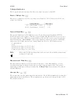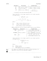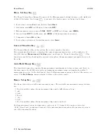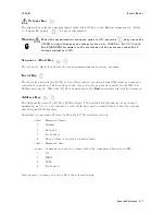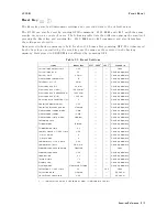
Front
P
anel
4339B
Show
Setting
K
ey
The
Show
Setting
Key
changes
the
mode
of
the
Measurement
Settings
display
on
the
right
side
of
the
LCD
display
.
Each
time
is
pressed,
the
display
mode
is
changed
as
follows:
1.
T
est
voltage
setting(V
out)
and
Current
limit(Clmt)
2.
A
veraging
rate(A
V
G)
and
Trigger
delay
time(DL
Y)
3.
Measurement
sequence
mode(SNGL,
CONT
or
OFF)
and
charge
time(CHRG)
4.
Interval
time(INTV)
and
Memory
size(MEM)
of
the
measurement
sequence
5.
Comparator
limits(Hi
and
Lo)
6.
T
est
voltage
setting
and
Current
monitor
value(Imon)
Current
Monitor
K
ey
The
Current
Monitor
Key
is
for
setting
the
current
monitor
function.
The
current
monitor
function
displays
the
current
measurement
value
on
the
right
side
of
the
LCD
display
(Measurement
Settings
area),
as
shown
in
\Show
Setting
Key
".
This
function
is
useful
for
checking
the
current
value
when
the
measurement
parameter
is
set
to
R ,
Rs
or
Rv .
A
uto/Hold
Range
K
ey
The
A
uto/Hold
range
key
toggles
the
measurement
ranging
mode
between
A
uto
and
Hold.
In
the
A
uto
mode
,
the
4339B
selects
the
optimum
measurement
range
automatically
within
5
measurement
cycles
.
In
the
Hold
mode
,
the
4339B
measurement
range
is
xed
at
the
range
you
select.
The
Hold
Range
annunciator(
9
)
indicates
the
current
mode
.
Range
Setup
K
ey
The
Range
Setup
key
sets
the
measurement
range
.
The
available
measurement
range
settings
are:
100
pA
(available
when
the
measurement
time
mode
is
Medium
or
Long)
1
nA
10
nA
100
nA
1
A
10
A
100
A
(available
when
the
measurement
time
mode
is
Short)
Each
measurement
range
can
measure
a
value
up
to
1.1
times
of
the
range
setup
value
.
\OVLD "(Over
Load)
is
displayed
instead
of
the
measurement
data
when
the
measured
value
is
out
of
the
measurable
range
.
3-10
Function
Reference
Summary of Contents for 4339B
Page 10: ......
Page 18: ... ᄌᦝ 0123 45 6789 8 A B C ᄌᦝ 3 DE FG H FG IJ B C K 9 C Copyright 2007 Agilent Technologies ...
Page 20: ......
Page 21: ......
Page 22: ......
Page 24: ......
Page 25: ......
Page 26: ......
Page 30: ......
Page 44: ......
Page 55: ...4339B Initial Inspection Figure 1 1 Power Cable Supplied Getting Started 1 11 ...
Page 212: ......
Page 220: ......
Page 230: ......
Page 256: ......
Page 268: ...Procedure 4339B Figure B 5 A1 Main Board B 8 Handler Interface Installation ...

