B
Handler
Interface
Installation
This
appendix
provides
the
electrical
characteristics
of
the
handler
interface
signals
,
and
how
to
set
up
the
handler
interface
board.
Electrical
Characteristics
Output
Signals
Each
DC
output
is
isolated
using
open
collector
output
opto-isolators
.
The
output
voltage
of
each
line
is
enabled
by
putting
pull-up
resistors
on
the
main
board,
and
by
connecting
the
pull-up
resistors
to
an
externally
applied
DC
voltage
.
The
electrical
circuits
of
the
DC
isolated
outputs
are
divided
into
two
groups
to
be
able
to
separate
power
supplies
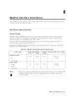
(refer
to
T
able
B-1 ).
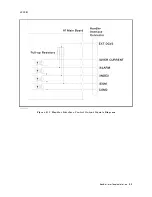
A
simplied
diagrams
of
the
output
signals
is
shown
in
Figure
B-1
for
comparison
signals
and
Figure
B-2
for
control
signals
.
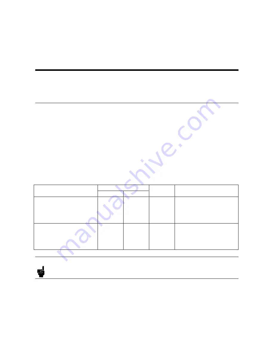
T
able
B-1.
Handler
Output
Electrical
Characteristics
Output
Signals
V
oltage
Output
Rating
Maximum
Current
External
V
oltage/Circuit
Common
Low
High
Comparison
Signals
/HI
/IN
/LO
/NO
CONT
A
CT
0.5
V
5
to
24
V
6
mA
EXT
DCV1
COM1
Control
Signals
/ALARM
/INDEX
/EOM
/NOT
READY
0.5
V
5
to
15
V
6
mA
EXT
DCV2
COM2
Note
The
pull-up
resistors
in
Figure
B-1
and
Figure
B-2
are
not
mounted
when
4339B
is
shipped
from
the
factory
.
Before
using
the
handler
interface
,
mount
the
pull-up
resistors
.
Handler
Interface
Installation
B-1
Summary of Contents for 4339B
Page 10: ......
Page 18: ... ᄌᦝ 0123 45 6789 8 A B C ᄌᦝ 3 DE FG H FG IJ B C K 9 C Copyright 2007 Agilent Technologies ...
Page 20: ......
Page 21: ......
Page 22: ......
Page 24: ......
Page 25: ......
Page 26: ......
Page 30: ......
Page 44: ......
Page 55: ...4339B Initial Inspection Figure 1 1 Power Cable Supplied Getting Started 1 11 ...
Page 212: ......
Page 220: ......
Page 230: ......
Page 256: ......
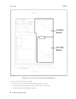
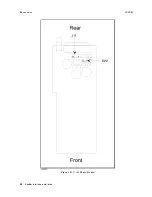
Page 268: ...Procedure 4339B Figure B 5 A1 Main Board B 8 Handler Interface Installation ...

