Overview
4339B
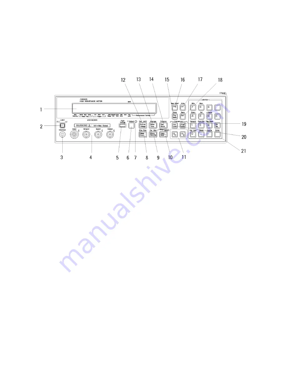
Front
P
anel
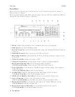
This
section
gives
a
guided
tour
of
the
front
panel.
F
or
a
detailed
description
of
each
key's
function,
refer
to
Chapter
3.
Each
description
starting
with
(Shift)
is
the
secondary
function
of
the
key
,
which
is
available
by
pressing
the
blue
shift
key
(refer
to
\Shift
Key").
1.
Display
displays
measurement
results
,
instrument
states
,
and
error
messages
.
2.
LINE
Switch
turns
the
4339B
ON
and
OFF
.
3.
Interlock
Connector
provides
safety
from
high
voltages
and
identies
which
test
xture
is
connected.
4.
UNKNO
WN
T
erminal
is
the
connection
port
of
the
test
xture
.
5.
High
V
oltage
Indicator
indicates
that
the
4339B
is
outputting
dangerous
voltage
levels
up
to
1000
Vdc
.
6.
V
oltage
Output
K
ey
applies
test
voltage
to
DUT
.
7.
V
oltage
Output
Indicator
indicates
when
voltage
is
applied
at
Output
terminal.
8.
Measurement
P
arameter
K
ey
selects
the
measurement
parameter
.
(Shift)
Electrode
Size
K
ey
denes
the
size
of
the
test
xture
electrode
.
9.
Show
Setting
K
ey
selects
the
mode
of
the
Measurement
Settings
display
on
the
right
side
of
the
LCD
display
.
(Shift)
Current
Monitor
K
ey
sets
the
current
monitor
.
10.
A
uto/Hold
K
ey
toggles
the
measurement
range
mode
between
A
uto
and
Hold.
(Shift)
Range
Setup
K
ey
selects
the
measurement
range
.
11.
Left/Down
and
Right/Up
Arrow
K
eys
increases
or
decreases
the
setting
value
.
12.
Source
V
oltage
K
ey
sets
the
value
of
the
applied
voltage
.
(Shift)
Current
Limit
K
ey
sets
the
limit
value
of
the
current
through
the
DUT
.
13.
Measurement
Time
K
ey
selects
measurement
time
mode
of
Short,
Medium,
or
Long.
(Shift)
A
verage
key
sets
the
averaging
rate
.
14.
Measurement
Sequence
Mode
K
ey
selects
the
measurement
sequence
mode
.
(Shift)
Program
K
ey
sets
the
measurement
sequence
.
1-4
Getting
Started
Summary of Contents for 4339B
Page 10: ......
Page 18: ... ᄌᦝ 0123 45 6789 8 A B C ᄌᦝ 3 DE FG H FG IJ B C K 9 C Copyright 2007 Agilent Technologies ...
Page 20: ......
Page 21: ......
Page 22: ......
Page 24: ......
Page 25: ......
Page 26: ......
Page 30: ......
Page 44: ......
Page 55: ...4339B Initial Inspection Figure 1 1 Power Cable Supplied Getting Started 1 11 ...
Page 212: ......
Page 220: ......
Page 230: ......
Page 256: ......
Page 268: ...Procedure 4339B Figure B 5 A1 Main Board B 8 Handler Interface Installation ...


