4339B
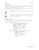
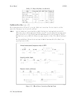
Front
P
anel
1.
At
the
Ready
state
,
pressing
starts
a
measurement
sequence
,
and
the
test
voltage
is
turned
ON.
2.
The
4339B
waits
for
the
dened
Charge
Time
while
the
applied
voltage
is
charging
the
DUT
.
3.
After
that,
the
4339B
repeats
measuring
the
DUT
as
many
times
as
is
dened
by
the
Memory
Size
with
a
dened
Interval
Time
between
measurements
.
The
measurement
data
is
displayed
on
the
LCD
display
after
each
measurement,
and
all
measurement
data
is
stored
in
the
data
buer
,
which
can
be
accessed
using
GPIB
commands
(refer
to
\D
A
T
A
Subsystem
"
in
Chapter
5).
4.
After
all
measurements
are
completed,
the
4339B
turns
the
test
voltage
OFF
,
and
returns
to
the
Ready
state
.
The
user
denable
parameters
Charge
Time,
Interval
Time
,
and
Memory
Size
,
are
set
using
the
program
key
(
).
F
or
details
,
refer
to
\Program
Key
".
When
the
sequence
is
running,
the
Seq
Running
annunciator(
9
)
turns
ON.
Program
K
ey
The
program
key
sets
the
parameters
for
a
measurement
sequence
.
F
or
details
about
the
measurement
sequence
,
refer
to
\Measurement
Sequence
Mode
Key
".
Y
ou
can
setup
the
measurement
sequence
parameters
in
the
following
menu:
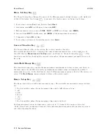
Chrg
The
Charging
time
of
voltage
.
The
range
and
resolution
are
as
follows:
Range
Resolution
0
s
Charge
Time
<
10
s
1
ms
10
s
Charge
Time
<
100
s
10
ms
100
s
Charge
Time
999
s
100
ms
The
default
setting
is
0
ms
.
Intvl
This
menu
is
for
setting
the
Interval
Time
and
the
Memory
Size
.
These
parameters
are
used
only
in
the
Continuous
mode
.
Interval
Time
The
range
and
resolution
are
as
follows:
Range
Resolution
10
ms
Interval
Time
<
10
s
1
ms
10
s
Interval
Time
<
100
s
10
ms
100
s
Interval
Time
999
s
100
ms
The
default
setting
is
1
s
.
Memory
Size
This
parameter
is
the
number
of
measurement
points
which
will
be
stored.
A
vailable
memory
sizes
are
1
to
500.
The
default
memory
size
is
500.
Function
Reference
3-7
Summary of Contents for 4339B
Page 10: ......
Page 18: ... ᄌᦝ 0123 45 6789 8 A B C ᄌᦝ 3 DE FG H FG IJ B C K 9 C Copyright 2007 Agilent Technologies ...
Page 20: ......
Page 21: ......
Page 22: ......
Page 24: ......
Page 25: ......
Page 26: ......
Page 30: ......
Page 44: ......
Page 55: ...4339B Initial Inspection Figure 1 1 Power Cable Supplied Getting Started 1 11 ...
Page 212: ......
Page 220: ......
Page 230: ......
Page 256: ......
Page 268: ...Procedure 4339B Figure B 5 A1 Main Board B 8 Handler Interface Installation ...

