background image

F

requency

Minimum

Limit

T

est

Result

T

est

Limit

Measuremen

t

Uncertain

t

y

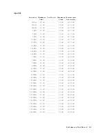
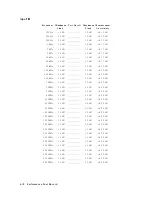
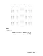
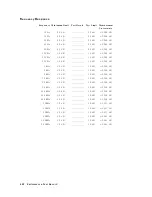
100

MHz

01.3

dB

1.3

dB

60.093

dB

125

MHz

01.3

dB

1.3

dB

60.093

dB

150

MHz

01.3

dB

1.3

dB

60.093

dB

175

MHz

01.3

dB

1.3

dB

60.110

dB

200

MHz

01.3

dB

1.3

dB

60.110

dB

225

MHz

01.3

dB

1.3

dB

60.110

dB

250

MHz

01.3

dB

1.3

dB

60.110

dB

275

MHz

01.3

dB

1.3

dB

60.110

dB

300

MHz

01.3

dB

1.3

dB

60.110

dB

325

MHz

01.3

dB

1.3

dB

60.110

dB

350

MHz

01.3

dB

1.3

dB

60.110

dB

375

MHz

01.3

dB

1.3

dB

60.110

dB

400

MHz

01.3

dB

1.3

dB

60.110

dB

425

MHz

01.3

dB

1.3

dB

60.110

dB

450

MHz

01.3

dB

1.3

dB

60.110

dB

475

MHz

01.3

dB

1.3

dB

60.110

dB

500

MHz

01.3

dB

1.3

dB

60.110

dB

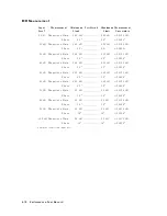
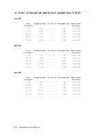
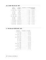
18.

SECOND

HARMONIC

DISTORTION

TEST

F

requency

T

est

Result

T

est

Limit

Measuremen

t

Uncertain

t

y

50.1

MHz

<

070

dBc

62.65

dB

19.

THIRD

ORDER

INTERMODULA

TION

DISTORTION

TEST

F

requency

T

est

Result

T

est

Limit

Measuremen

t

Uncertain

t

y

100.2

MHz

<

070

dBc

64.3

dB

P

erformance

T

est

Record

4-23

Summary of Contents for 4395A

Page 1: ...ERS This manual applies directly to instruments with serial number pre x JP1KE02197 or above and MY41100220 or above For additional important information about serial numbers read Serial Number in Appendix A Agilent Part No 04395 90120 Printed in Japan August 2002 Fifth Edition ...

Page 2: ...pyright All rights are reserved No part of this document may be photocopied reproduced or translated to another language without the prior written consent of the Agilent Technologies Company Agilent Technologies Japan LTD Kobe Instrument Division 1 3 2 Murotani Nishi Ku Kobe shi Hyogo 651 2241 Japan c Copyright 1998 2000 2002 Agilent Technologies Japan Ltd ...

Page 3: ...ncorporated at reprint do not cause the date to change The manual part number changes when extensive technical changes are incorporated February 1998 First Edition Part Number 04395 90100 September 1998 Second Edition Part Number 04395 90110 June 2000 Third Edition Part Number 04395 90110 March 2001 Fourth Edition Part Number 04395 90110 August 2002 Fifth Edition Part Number 04395 90120 iii ...

Page 4: ...lectric shock hazard the instrument chassis and cabinet must be connected to a safety earth ground by the supplied power cable with earth blade DO NOT Operate In An Explosive Atmosphere Do not operate the instrument in the presence of ammable gasses or fumes Operation of any electrical instrument in such an environment constitutes a de nite safety hazard Keep Away From Live Circuits Operating pers...

Page 5: ... symbol when it is necessary for the user to refer to the instruction manual Alternating current Direct current On Supply O Supply In position of push button switch Out position of push button switch Frame or chassis terminal A connection to the frame chassis of the equipment which normally include all exposed metal structures This Warning sign denotes a hazard It calls attention to a procedure pr...

Page 6: ...o a service facility designated by Agilent Technologies Buyer shall prepay shipping charges to Agilent Technologies and Agilent Technologies shall pay shipping charges to return the product to Buyer However Buyer shall pay all shipping charges duties and taxes for products returned to Agilent Technologies from another country Agilent Technologies warrants that its software and rmware designated by...

Page 7: ... incidental or consequential damages whether based on contract tort or any other legal theory Assistance Product maintenance agreements and other customer assistance agreements are available for Agilent Technologies products For any assistance contact your nearest Agilent Technologies Sales and Service O ce Addresses are provided at the back of this manual vii ...

Page 8: ...es when a name or a variable must be typed in place of the words in italics For example copy lename means to type the word copy to type a space and then to type the name of a le such as file1 Computer Computer font is used for on screen prompts and messages 4HARDKEYS5 Labeled keys on the instrument front panel are enclosed in 4 5 NNNNNNNNNNNNNNNNNNNNNNNNNN SOFTKEYS Softkeys located to the right of...

Page 9: ... the analyzer and describes how HP Instrument BASIC works with the analyzer HP Instrument BASIC Users Handbook Agilent Part Number E2083 90005 The HP Instrument BASIC User s Handbook introduces you to the HP Instrument BASIC programming language provide some helpful hints on getting the most use from it and provide a general programming reference It is divided into three books HP Instrument BASIC ...

Page 10: ......

Page 11: ...2 2 Description 2 2 Speci cation 2 2 Test Equipment 2 2 Procedure 2 2 2 SOURCE LEVEL ACCURACY FLATNESS TEST NA 2 4 Description 2 4 Speci cation 2 4 Test Equipment 2 4 Procedure 2 4 3 NON SWEEP POWER LINEARITY TEST NA 2 8 Description 2 8 Speci cation 2 8 Test Equipment 2 8 Procedure 2 8 4 POWER SWEEP LINEARITY TEST NA 2 11 Description 2 11 Speci cation 2 11 Test Equipment 2 11 Procedure 2 11 5 HARM...

Page 12: ... PHASE DYNAMIC ACCURACY TEST NA 2 36 Description 2 36 Speci cation 2 36 Test Equipment 2 36 Procedure 2 37 12 MAGNITUDE RATIO PHASE FREQUENCY RESPONSE TEST NA 2 45 Description 2 45 Speci cation 2 45 Test Equipment 2 45 Procedure 2 45 13 DISPLAYED AVERAGE NOISE LEVEL TEST SA 2 50 Description 2 50 Speci cation 2 50 Test Equipment 2 50 Procedure 2 50 14 AMPLITUDE FIDELITY TEST SA 2 53 Description 2 5...

Page 13: ...peci cation 2 79 Test Equipment 2 79 Procedure 2 79 3 Calculation Sheet INTRODUCTION 3 1 2 SOURCE LEVEL ACCURACY FLATNESS TEST 3 1 Level Accuracy 3 1 Level Flatness 3 2 3 NON SWEEP POWER LINEARITY TEST 3 3 Reference 0 dBm 3 3 Non Sweep Power Linearity 3 3 4 POWER SWEEP LINEARITY TEST 3 4 6 DC BIAS TEST Option 001 3 5 DC Bias Voltage Level Accuracy 3 5 DC Bias Current Level Accuracy 3 5 7 RECEIVER ...

Page 14: ...t 50 MHz 3 18 At Frequencies 1 MHz 3 19 At Frequencies 1 MHz 3 20 Input A 3 20 Reference at 50 MHz 3 20 At Frequencies 1 MHz 3 21 At Frequencies 1 MHz 3 22 Input B 3 22 Reference at 50 MHz 3 22 At Frequencies 1 MHz 3 23 At Frequencies 1 MHz 3 24 18 THIRD ORDER HARMONIC DISTORTION TEST 3 24 4 Performance Test Record 1 FREQUENCY ACCURACY TEST 4 1 without Option 1D5 4 1 with Option 1D5 4 1 2 SOURCE L...

Page 15: ...4 13 Input R 4 13 Input A 4 14 Input B 4 14 14 AMPLITUDE FIDELITY TEST 4 14 Input R 4 15 Input A 4 15 Input B 4 15 15 INPUT ATTENUATOR SWITCHING UNCERTAINTY TEST 4 16 Input R 4 16 Input A 4 16 Input B 4 16 16 NOISE SIDEBANDS TEST 4 17 Input R 4 17 17 AMPLITUDE ACCURACY FREQUENCY RESPONSE TEST 4 18 Input R 4 18 Level Accuracy 4 18 Frequency Response 4 18 Input A 4 19 Level Accuracy 4 19 Frequency R...

Page 16: ...ed Equipment 5 10 Procedure 5 10 Required Equipment 5 10 Procedure 5 10 3 Local DAC Adjustment 5 13 Required Equipment 5 13 Procedure 5 13 4 Source Power Adjustment 5 14 Required Equipment 5 14 Procedure 5 14 5 Source Flatness Adjustment 5 15 Required Equipment 5 15 Procedure 5 15 6 Input DC O set Adjustment 5 16 Required Equipment 5 16 Procedure 5 16 7 Input Local Null Adjustment 5 18 Required Eq...

Page 17: ...t 6 6 Execute All Internal Tests 6 6 Execute the Individual Test 6 6 External Tests Failure Troubleshooting 6 8 Performance Tests Failure Troubleshooting 6 9 Perform Adjustments and Correction Constants 6 9 7 Power Supply Troubleshooting INTRODUCTION 7 1 START HERE 7 3 1 Check the Fan is Rotating 7 3 2 Check the A50 SHUTDOWN LED 7 3 A50 Shutdown LED 7 4 3 Check the A1 5 VD LED 7 4 Measure the A1 5...

Page 18: ...k the A53 FDD 8 10 7 Check the A32 I BASIC Interface and the mini DIN Keyboard 8 10 8 Check the A33 EXT I O Interface 8 11 TROUBLESHOOT THE A51 GSP and A52 LCD 8 12 1 Run the Internal Test 3 A51 GSP 8 12 2 Check the A52 LCD Liquid Crystal Display 8 12 9 Accessories Troubleshooting INTRODUCTION 9 1 VERIFY OPERATIONS 9 2 Using 75 Connectors with 50 Connectors 9 2 Large Spurious Signals in the Spectr...

Page 19: ...ge 1 A 3 Change 2 A 7 Change 3 A 8 Change 4 A 9 Fuse Selection A 10 Change 5 A 11 Change 6 A 13 Serial Number A 17 B Power Requirement Replacing Fuse B 1 Fuse Selection B 1 Power Requirements B 2 Power Cable B 2 Messages Error Messages in Alphabetical Order Messages 1 Error Messages in Numerical Order Messages 16 Index Contents 9 ...

Page 20: ...t Setup 2 46 2 19 B R Magnitude Ratio Phase Frequency Response Test Setup 2 48 2 20 Average Noise Level Test Setup 2 50 2 21 Amplitude Fidelity Test Setup 1 2 54 2 22 Input Attenuator Accuracy Test Setup 2 59 2 23 Noise Sidebands Test Setup 2 62 2 24 Frequency Response Test Setup 1 2 66 2 25 Frequency Response Test Setup 2 2 68 2 26 Frequency Response Test Setup 3 2 69 2 27 Second Harmonics Distor...

Page 21: ...s Pattern 8 7 8 6 Bootloader Display 8 9 9 1 Probe Power Connector Voltages 9 5 10 1 Top View Major Assemblies 10 4 10 2 Bottom View Major Assemblies 10 6 10 3 Angle Assembly Parts 1 5 10 7 10 4 Angle Assembly Parts 2 5 10 8 10 5 Angle Assembly Parts Opt 001 3 5 10 9 10 6 Angle Assembly Parts 4 5 10 10 10 7 Angle Assembly Parts 5 5 10 11 10 8 Front Assembly Parts 1 8 10 12 10 9 Front Assembly Part...

Page 22: ...DC Converter Assembly 17 23 10 44 10 41 Main Frame Assembly Parts A5 and A7 Assemblies 18 23 10 45 10 42 Main Frame Assembly Parts A2 DC Bias Assembly 19 23 10 46 10 43 Main Frame Assembly Parts YTO Assembly 20 23 10 47 10 44 Main Frame Assembly Parts YTO Assembly 21 23 10 48 10 45 Main Frame Assembly Parts YTO Assembly 22 23 10 49 10 46 Main Frame Assembly Parts 23 23 10 50 A 1 Front Assembly Par...

Page 23: ...est Settings 2 2 44 2 18 Displayed Average Noise Level Test Settings 2 51 2 19 Amplitude Fidelity Test Settings 2 55 2 20 Input Attenuator Switching Uncertainty Test Settings 2 60 2 21 Noise Sideband Test Settings 2 63 2 22 Frequency Response Test Settings 1 2 67 2 23 Frequency Response Test Settings 2 2 70 2 24 Other Spurious Test Settings 2 77 2 25 Residual Response Test Settings 2 80 5 1 Requir...

Page 24: ... Frame Assembly Parts 9 23 10 36 10 35 Main Frame Assembly Parts A1 CPU Board Assembly 10 23 10 37 10 36 Main Frame Assembly Parts 11 23 10 38 10 37 Main Frame Assembly Parts 12 23 10 39 10 38 Main Frame Assembly Parts A9 Input Multiplexer Assembly 13 23 10 40 10 39 Main Frame Assembly Parts 14 23 10 41 10 40 Main Frame Assembly Parts 15 23 10 42 10 41 Main Frame Assembly Parts Pre regulator Assem...

Page 25: ...8 A 11 A 12 Front Assembly Parts 4 8 A 12 A 13 Top View Major Assemblies A 14 A 14 Main Frame Assembly Parts A5 and A7 Assemblies 18 23 A 15 A 15 Main Frame Assembly Parts YTO Assembly 20 23 A 16 B 1 Fuse Selection B 1 Contents 15 ...

Page 26: ......

Page 27: ... or replacement of an assembly Some of the adjustments updates correction constants stored into the Flash ROM on the A1 CPU board The correction constants is updated by using the adjustment program PN 04395 18004 Note The next four four chapters are the core troubleshooting chapters Troubleshooting The troubleshooting strategy is to systematically verify portions of the analyzer and thus narrow do...

Page 28: ...ontains the table of related service procedures It is a table of adjustments and veri cation procedures to be performed after repair or replacement of each assembly Appendices contains the manual changes information required to make this manual compatible with earlier shipment con gurations of the analyzer the motherboard pin assignment list and the power requirement Messages contains the service ...

Page 29: ...0 Absolute Amplitude Accuracy Test NA 11 Magnitude Ratio Phase Dynamic Accuracy Test NA 12 Magnitude Ratio Phase Frequency Response Test NA 13 Displayed Average Noise Level Test SA 14 Amplitude Fidelity Test SA 15 Input Attenuator Switching Uncertainty Test SA 16 Noise Sidebands Test SA 17 Amplitude Accuracy Frequency Response Test SA 18 Second Harmonic Distortion Test SA 19 Third Order Intermodul...

Page 30: ...if applicable The measurement uncertainty shows how accurately the analyzer s speci cations are measured and depends on the test equipment used The listed measurement uncertainties are valid only when the recommended equipment is used How to Use The following procedure is recommended when using the calculation sheet and the performance test record 1 Make extra copies of the calculation sheet and t...

Page 31: ... Range 1 MHz to 500 MHz Power 060 dBm to 035 dBm 8481D 1 Function Genarator Frequency Range 10 Hz to 500 kHz Level Accuracy 60 2 dB Return loss 20 dB 3325A 1 Multimeter No substitute 3458A 1 Signal Generator Frequency Range 1 MHz to 500 MHz SSB Phase Noise at 100 Hz o set 0112 dBc Hz SSB Phase Noise at 1 kHz o set 0121 dBc Hz 8663A 1 Signal Generator Frequency Range 50 MHz to 100 2 MHz SSB Phase N...

Page 32: ... Data Required for Step Attenuators later in this chapter 4 An 8496G step attenuator with required low VSWR 1 02 can be purchased by specifying option H60 5 Required when an 8496G step attenuator is used in the tests 6 The 85032B includes a type N m 50 termination 7 An 8491A Opt 006 xed attenuator with required low VSWR 1 015 can be purchased by specifying Opt H60 8 An 8491A Opt 010 xed attenuator...

Page 33: ... the third column of Table 1 3 The calibration of step attenuators 8496G Opt 001 and H60 are available at Agilent Technologies For information about the calibration and the available uncertainties contact your nearest Agilent Technologies service center Note The 8496G Opt 001 and H60 programmable step attenuator has four attenuation segments 10 dB segment 20 dB segment and two 40 dB segments Each ...

Page 34: ......

Page 35: ...ng parts Description describes the test procedure Speci cation describes the performance veri ed in the test Test Equipment describes test equipment required in the test Procedure describes the test procedure step by step Note Allow the analyzer to warm up for at least 30 minutes before you execute any of the performance tests Perform all performance tests in an ambient temperature of 23 6 5 C Not...

Page 36: ... 1D5 Frequency Counter 5334B BNC cable 61 cm PN 8120 1839 N m BNC f adapter PN 1250 0780 For testing an 4395A equipped with Opt 1D5 Frequency Counter 5334B Frequency Standard 5061B 1 BNC cable 61 cm PN 8120 1839 BNC cable 122 cm PN 8120 1840 N m BNC f adapter PN 1250 0780 1 The 5061B can be replaced with any 10 MHz frequency standard with time base error of 6 1 x 10010 year Procedure 1 Connect the...

Page 37: ...NNNNNNNNNNNNNNNN NETWORK ANALYZER 4Preset5 to initialize the 4395A Then set the controls as follows Control Settings Key Strokes Center Frequency 100 MHz 4Center5 415 405 405 4M 5 Frequency Span ZERO 4Span5 NNNNNNNNNNNNNNNNNNNNNNNNNNNNN ZERO SPAN The source power now is set to 0 dBm preset value 4 Press 4Trigger5 NNNNNNNNNNNNNNNNNNNN SINGLE to make a sweep Wait for the frequency counter reading to...

Page 38: ...he power reading taken at 50 MHz Specification Level accuracy 2365 C 50 MHz 0 dBm output 61 0 dB Flatness 2365 C relative to 50 MHz 0 dBm output 62 0 dB Test Equipment Power Meter 436A Opt 022 437B or 438A Power Sensor 8482A Multimeter 3458A 50 Feedthrough PN 04192 61002 BNC cable 61 cm PN 8120 1839 N m BNC f adapter PN 1250 0780 BNC f Dual Banana Plug Adapter PN 1251 2277 Procedure 1 Connect the ...

Page 39: ...ce power now is set to 0 dBm preset value 4 Source Level Accuracy Test a Wait for the power meter reading to settle b Record the power meter reading in the performance test record Test Result column for the level accuracy test 5 Source Level Flatness Test High Frequencies a Record the test result of the level accuracy test in the calculation sheet Power Meter Reading ref column for the level atnes...

Page 40: ...ng in the calculation sheet Power Meter Reading column d Change the 4395A center frequency in accordance with Table 2 1 and repeat step 5 c for each frequency e Calculate test results using the equation given in the calculation sheet Record the test results in the performance test record 6 Source Level Flatness Test Low Frequencies a Connect the test equipment as shown in Figure 2 3 Figure 2 3 Sou...

Page 41: ...2 lists atness test points for low frequencies Table 2 2 Source Level Flatness Test Settings 2 4395A Center Frequency 10 Hz 50 Hz 500 Hz 2 kHz 12 kHz 60 kHz 160 kHz 500 kHz d Wait for the multimeter reading to settle Then record the reading in the calculation sheet Power Meter Reading column e Change the 4395A center frequency in accordance with Table 2 2 and repeat step 6 d for each frequency f C...

Page 42: ...n values of the step attenuator at 50 MHz Specification Level linearity Output Power Linearity1 040 dBm power 61 0 dB power 040 dBm 61 5 dB 1 2365 C relative to 0 dBm output Test Equipment Power Meter 436A Opt 022 437B or 438A Power Sensor 8481D Type N Cable 61 cm 11500B or part of 11851B Step Attenuator1 10 dB Step VSWR 1 02 8496G Opt 001 and H60 Attenuator driver 11713A 1 Calibration values for ...

Page 43: ...NNNNNNNNNNNNNNNNNN ZERO SPAN The source power now is set to 0 dBm preset value 6 Set the step attenuator to the rst setting 30 dB listed in the second column of Table 2 3 7 Wait for the power meter reading to settle 8 Record the power meter reading in the calculation sheet Use Power Meter Reading column of the calculation sheet for the reference 0 dBm Table 2 3 Non Sweep Power Linearity Test Setti...

Page 44: ...ing in the calculation sheet Use Power Meter Reading column of the calculation sheet for the non sweep power linearity test 10 Repeat step 9 for each setting 11 Calculate the test results using the equations given in the calculation sheet Record the test results in the performance test record 2 10 Performance Tests ...

Page 45: ...ncertainty caused by the power sensor s linearity error The actual power of the RF OUT signal is calculated by adding the attenuation used and the power meter reading Specification Sweep range 20 dB Sweep linearity 2365 C 50 MHz relative to stop power 60 5 dB Test Equipment Power Meter 436A Opt 022 437B or 438A Power Sensor 8481D Step Attenuator 10 dB Step VSWR 1 02 8496G Opt 001 and H60 Attenuato...

Page 46: ...rigger Manual 4Trigger5 NNNNNNNNNNNNNNNNNNNNNNNNNNNNNNNNNNNNNN TRIGGER xxx NNNNNNNNNNNNNNNNNNNN MANUAL Trigger Event On Point 4Trigger5 NNNNNNNNNNNNNNNNNNNNNNNNNNNNNNNNNNNNNN TRIGGER xxx NNNNNNNNNNNNNNNNNNNNNNNNNNNNNNNNNNNNNNNNNNNNNNNNNNNNNNNNNNNNNNNNN TRIG EVENT ON SWEEP Then the softkey label changes to NNNNNNNNNNNNNNNNNNNNNNNNNNNNNNNNNNNNNNNNNNNNNNNNNNNNNNNN TRIGGER ON POINT 5 Press 4Trigger5 N...

Page 47: ...NNNNNNNNNNNNNNN TRIGGER xxx NNNNNNNNNNNNNNNNNNNN MANUAL Trigger Event On Point 4Trigger5 NNNNNNNNNNNNNNNNNNNNNNNNNNNNNNNNNNNNNN TRIGGER xxx NNNNNNNNNNNNNNNNNNNNNNNNNNNNNNNNNNNNNNNNNNNNNNNNNNNNNNNNNNNNNNNNN TRIG EVENT ON SWEEP Then the softkey label changes to NNNNNNNNNNNNNNNNNNNNNNNNNNNNNNNNNNNNNNNNNNNNNNNNNNNNNNNN TRIGGER ON POINT 10 Press 4Trigger5 NNNNNNNNNNNNNNNNNNNN SINGLE NNNNNNNNNNNNNNNNNNN...

Page 48: ...ading to settle c Record the power meter reading in the calculation sheet 14 Calculate the test results using the equation given in the calculation sheet Record the test results in the performance test record 2 14 Performance Tests ...

Page 49: ...equency is set to values where harmonics and non harmonic spurious are most likely to be observed Specification Spectral Purity Characteristics Harmonics 10 dBm output 030 dBc Non harmonics spurious 10 dBm output 030 dBc Test Equipment Spectrum Analyzer 8566A B Type N Cable 61 cm 11500B or part of 11851B BNC cable 122 cm PN 8120 1840 Procedure 1 Connect the test equipment as shown in Figure 2 6 Fi...

Page 50: ...ists test frequencies Table 2 6 Harmonics Test Settings 4395A Center Frequency Spectrum Analyzer 2nd Harmonics 3rd Harmonics Frequency RBW Frequency Frequency Span 10 kHz 20 kHz 30 kHz 1 kHz 30 Hz 500 kHz 1 MHz 1 5 MHz 1 kHz 30 Hz 10 MHz 20 MHz 30 MHz 1 kHz 30 Hz 100 MHz 200 MHz 300 MHz 1 kHz 30 Hz 250 MHz 500 MHz 750 MHz 1 kHz 30 Hz 500 MHz 1 0 GHz 1 5 GHz 1 kHz 30 Hz b On the spectrum analyzer p...

Page 51: ... 1 kHz 30 Hz 330 MHz 500 MHz 1 kHz 30 Hz 430 MHz 400 MHz 1 kHz 30 Hz 500 MHz 330 MHz 1 kHz 30 Hz c On the spectrum analyzer perform the following steps to measure the non harmonic spurious level of the rst test frequency 10 Hz d Perform the following steps to test non harmonics spurious of 4395A i Set the 8566A B center frequency to the same value as the 4395A center frequency ii Set the 8566A B f...

Page 52: ...A 125 mV Current 2365 C 6 0 5 30 A Vdc2 V 10 k mA 1 Current at DC source connector 2 Voltage at DC source connector Test Equipment Multimeter 3458A BNC cable 61 cm PN 8120 1839 N m BNC f adapter PN 1250 0780 BNC f Dual Banana Plug Adapter PN 1251 2277 Procedure 1 DC Bias Voltage Level Test a Connect the test equipment as shown in Figure 2 7 Figure 2 7 DC Bias Voltage Level Test Setup 2 18 Performa...

Page 53: ...ings 4395A DC Level 4395A DC Current Limit Multimeter Range Auto Range 040 V 100 mA 100 V 010 V 100 mA 10 V 04 V 100 mA 10 V 0 V 100 mA 1 V 4 V 100 mA 10 V 10 V 100 mA 10 V 40 V 100 mA 100 V e Wait for the multimeter reading to settle Then record the reading in the calculation sheet Multimeter Reading column f Change the setting of the 4395A and the multimeter in accordance with Table 2 8 and repe...

Page 54: ...oltage Limit Multimeter Range Auto Range 0100 mA 20 V 100 mA 010 mA 20 V 10 mA 01 mA 20 V 1 mA 020 A 20 V 100 A 20 A 20 V 100 A 1 mA 20 V 1 mA 10 mA 20 V 10 mA 100 mA 20 V 100 mA d Wait for the multimeter reading to settle Then record the reading in the calculation sheet Multimeter Reading column e Change the setting of the 4395A and the multimeter in accordance with Table 2 9 and repeat step 2 d ...

Page 55: ... linear format Unit Then the measured values are converted to log magnitude format dBm This is done to avoid skewing the data with the marker statistics function Specification Noise level Noise Level Frequency IFBW 10 Hz 100 freq 100 kHz 085 dBm 100 kHz freq 0115 f 1 100 dBm 1 f is measurement frequency MHz Test Equipment 50 Termination three required 909C Opt 012 or part of 85032B Procedure 1 Con...

Page 56: ...NNNNNNNNNNNNNNNNN SCALE DIV 455 4M 5 Input Attenuator B 10 dB 4Scale Ref5 NNNNNNNNNNNNNNNNNNNNNNNNNNNNNNNNNNNNNNNNNNNNNNN ATTENUATOR MENU NNNNNNNNNNNNNNNNNNNNNNN ATTEN B 415 405 4x15 Source Power 050 dBm 4Source5 NNNNNNNNNNNNNNNNN POWER 4 5 455 405 4x15 Frequency Span 0 Hz 4Span5 NNNNNNNNNNNNNNNNNNNNNNNNNNNNN ZERO SPAN IF BW 10 Hz 4Bw Avg5 NNNNNNNNNNNNNNNNN IF BW 415 405 4x15 Number of Points 51 4...

Page 57: ... Unit in the calculation sheet Trace Mean column g Press 4Meas5 NNNNN B to set the 4395A input to B input h Press 4Trigger5 NNNNNNNNNNNNNNNNNNNN SINGLE to make a sweep Wait for the completion of the sweep i Record the 4395A trace mean value Unit in the calculation sheet Trace Mean column 5 Change the 4395A center frequency in accordance with Table 2 10 and repeat step 4 for each setting 6 Convert ...

Page 58: ... Termination two required 909C Opt 012 or part of 85032B Procedure 1 Connect the test equipment as shown in Figure 2 10 Figure 2 10 Input Crosstalk Test Setup 2 Press 4Meas5 NNNNNNNNNNNNNNNNNNNNNNNNNNNNNNNNNNNNNNNNN ANALYZER TYPE NNNNNNNNNNNNNNNNNNNNNNNNNNNNNNNNNNNNNNNNNNNNNNNNNN NETWORK ANALYZER 4Preset5 to initialize the 4395A Then set the controls as follows Control Settings Key Strokes Dual Ch...

Page 59: ...y to the rst test setting 10 kHz listed in Table 2 11 5 Press 4Bw Avg5 NNNNNNNNNNNNNNNNN IF BW 425 4x15 to set the IF Bandwidth to the rst test setting 2 Hz listed in Table 2 11 6 Press 4Sweep5 NNNNNNNNNNNNNNNNNNNNNNNNNNNNNNNNNNNNNNNNNNNNNNNNNN NUMBER of POINTS 415 415 4x15 to set the number of points to the rst test setting 11 listed in Table 2 11 Table 2 11 Input Crosstalk Test Test Settings Sta...

Page 60: ...ess 4Sweep5 NNNNNNNNNNNNNNNNNNNNNNNNNNNNNNNNNNNNNNNNNNNNNNNNNNNNN COUPLED CH ON off change the 4395A test settings in accordance with the Table 2 11 and repeat step 7 for each setting 2 26 Performance Tests ...

Page 61: ...s Therefore a network analyzer is used in this test Specification Return Loss att 10 dB Return Loss Frequency att 10 dB 100 kHz freq 100 MHz 25 dB 100 MHz freq 15 dB Test Equipment Network Analyzer 8753A B C T R Test Sets 85044A 50 Type N Calibration Kit 85032B1 APC7 5 N f adapter 11524A or part of 85032B Type N Cable 61 cm four required 11500B or part of 11851B 1 This calibration kit includes sev...

Page 62: ... network analyzer controls to measure the return loss from 300 kHz to 100 MHz a Press 4Preset5 to initialize the network analyzer b Press 4Start5 435 405 405 4k m5 c Press 4Stop5 415 405 405 4M 5 d Press 4Menu5 NNNNNNNNNNNNNNNNNNNNNNNNNNNNNNNNNNNNNNNNNNNNNNN SWEEP TYPE MENU NNNNNNNNNNNNNNNNNNNNNNNNNN LOG FREQ e Press 4Avg5 NNNNNNNNNNNNNNNNN IF BW 415 405 405 4x15 f Press 4CAL5 NNNNNNNNNNNNNNNNNNNN...

Page 63: ... 12 Remove the test port cable from the 4395A A input and connect it to the B input 13 On the network analyzer press 4MENU5 NNNNNNNNNNNNNNNNNNNNNNNNNNNNNNNNNNNNNN TRIGGER MENU NNNNNNNNNNNNNNNNNNNN SINGLE to make a sweep Wait for the completion of the sweep 14 On the network analyzer press 4MKR FCTN5 NNNNNNNNNNNNNNNNNNNNNNNNNNNNNNNNNNNNNNNNNNNNNNNNNN MKR SEARCH OFF NNNNNNNNNNN MAX to move the marke...

Page 64: ... input and connect it to the A input 22 On the network analyzer press 4MENU5 NNNNNNNNNNNNNNNNNNNNNNNNNNNNNNNNNNNNNN TRIGGER MENU NNNNNNNNNNNNNNNNNNNN SINGLE to make a sweep Wait for the completion of the sweep 23 On the network analyzer press 4MKR FCTN5 NNNNNNNNNNNNNNNNNNNNNNNNNNNNNNNNNNNNNNNNNNNNNNNNNN MKR SEARCH OFF NNNNNNNNNNN MAX to move the marker to the maximum point on the trace 24 Record t...

Page 65: ...F OUT signal is divided through a two way power splitter and applied to an 4395A input and the power sensor input or the multimeter Specification Absolute amplitude accuracy R A B 010 dBm input input att 10 dB 2365 C freq 100 Hz IFBW 3 kHz 61 5 dB Test Equipment Power Meter 436A Opt 022 437B or 438A Power Sensor 8482A Multimeter 3458A Two Way Power Splitter 11667A 50 Feedthrough PN 04192 61002 Typ...

Page 66: ...5 NNNNNNNNNNNNNNNNNNNNNNNNNNNNNNNNNNNNNNNNNNNNNNN ATTENUATOR MENU NNNNNNNNNNNNNNNNNNNNNNN ATTEN R 415 405 4x15 Input Attenuator A 10dB 4Scale Ref5 NNNNNNNNNNNNNNNNNNNNNNNNNNNNNNNNNNNNNNNNNNNNNNN ATTENUATOR MENU NNNNNNNNNNNNNNNNNNNNNNN ATTEN A 415 405 4x15 Input Attenuator B 10dB 4Scale Ref5 NNNNNNNNNNNNNNNNNNNNNNNNNNNNNNNNNNNNNNNNNNNNNNN ATTENUATOR MENU NNNNNNNNNNNNNNNNNNNNNNN ATTEN B 415 405 4x15...

Page 67: ...395A Reading column and Meter Reading column respectively The trace mean value is displayed as a marker statistic mean in the upper right hand corner of the display v Change the 4395A center frequency and IF Bandwidth in accordance with Table 2 12 and repeat steps 1 e iii and 1 e iv for each center frequency f Remove the power splitter from the R input and connect it directly to the A input g Pres...

Page 68: ...5 NNNNNNNNNNNNNNNNNNNNNNNNNNNNNNNNNNNNNNNNNNNNNNN ATTENUATOR MENU NNNNNNNNNNNNNNNNNNNNNNN ATTEN A 415 405 4x15 Input Attenuator B 10dB 4Scale Ref5 NNNNNNNNNNNNNNNNNNNNNNNNNNNNNNNNNNNNNNNNNNNNNNN ATTENUATOR MENU NNNNNNNNNNNNNNNNNNNNNNN ATTEN B 415 405 4x15 Number of Points 11 4Sweep5 NNNNNNNNNNNNNNNNNNNNNNNNNNNNNNNNNNNNNNNNNNNNNNNNNN NUMBER of POINTS 415 415 4x15 Frequency Span 0 Hz 4Span5 NNNNNNNN...

Page 69: ...he trace mean value is displayed as a marker statistic mean in the upper right hand corner of the display iv Change the 4395A center frequency in accordance with Table 2 13 and repeat steps 2 e ii and 2 e iii for each center frequency f Remove the power splitter from the R input and connect it directly to the A input g Press 4Meas5 NNNNN A to set the 4395A to the A input h Repeat step 2 e to test ...

Page 70: ...xed attenuators with a VSWR 1 015 are used Using these attenuators reduces the measurement uncertainties caused by mismatch error When they are used the measurement uncertainties listed in the performance test record are valid Specification Magnitude ratio phase dynamic accuracy A R B R Input Level relative to full scale input level 0 10 dB Magnitude Ratio Dynamic Accuracy1 Phase Dynamic Accuracy1...

Page 71: ...NNNNNNNNNNNNNNNNNNNN DUAL CHAN ON off Marker DISCRETE 4Marker5 NNNNNNNNNNNNNNNNNNNNNNNNNNNNNNNN MKR CONT Then the softkey label changes to NNNNNNNNNNNNNNNNNNNNNNNNNNNNNNNNNNNNNNNNNNNN MKR DISCRETE Start Frequency 3 MHz 4Start5 435 4M 5 Stop Frequency 50 1 MHz 4Stop5 455 405 4 5 415 4M 5 IF BW 10 Hz 4Bw Avg5 NNNNNNNNNNNNNNNNN IF BW 415 405 4x15 Number of Points 2 4Sweep5 NNNNNNNNNNNNNNNNNNNNNNNNNNN...

Page 72: ... 0 dB d Press 4Cal5 NNNNNNNNNNNNNNNNNNNNNNNNNNNNNNNNNNNNNNNNNNNN CALIBRATE MENU NNNNNNNNNNNNNNNNNNNNNNNNNN RESPONSE NNNNNNNNNNNNNN THRU to perform the response THRU calibration Wait for the completion of the sweep Then press NNNNNNNNNNNNNNNNNNNNNNNNNNNNNNNNNNNNNNNNN DONE RESPONSE e Set the step attenuator to the rst setting 10 dB in the second column of Table 2 14 Table 2 14 A R Dynamic Accuracy T...

Page 73: ...VERAGING FACTOR 445 4x15 Input Attenuator R 10dB 4Scale Ref5 NNNNNNNNNNNNNNNNNNNNNNNNNNNNNNNNNNNNNNNNNNNNNNN ATTENUATOR MENU NNNNNNNNNNNNNNNNNNNNNNN ATTEN R 415 405 4x15 Input Attenuator A 0dB 4Scale Ref5 NNNNNNNNNNNNNNNNNNNNNNNNNNNNNNNNNNNNNNNNNNNNNNN ATTENUATOR MENU NNNNNNNNNNNNNNNNNNNNNNN ATTEN A 405 4x15 j Set the step attenuator to 10 dB k Press 4Cal5 NNNNNNNNNNNNNNNNNNNNNNNNNNNNNNNNNNNNNNNNN...

Page 74: ... marker to 50 1 MHz iii Record the channel 1 marker reading in the calculation sheet for the magnitude ratio dynamic accuracy Use the 4395A reading column corresponding to the input level in the rst column of Table 2 15 iv Press 4 5 to move the channel 2 marker to 3 MHz v Record the channel 2 marker reading directly in the performance test record Use the test result column of the phase measurement...

Page 75: ...NNNNNNNNNNNNNNNNNNNNNNNNNNN AVERAGING ON off Input Attenuator R 0dB 4Scale Ref5 NNNNNNNNNNNNNNNNNNNNNNNNNNNNNNNNNNNNNNNNNNNNNNN ATTENUATOR MENU NNNNNNNNNNNNNNNNNNNNNNN ATTEN R 405 4x15 Input Attenuator B 0dB 4Scale Ref5 NNNNNNNNNNNNNNNNNNNNNNNNNNNNNNNNNNNNNNNNNNNNNNN ATTENUATOR MENU NNNNNNNNNNNNNNNNNNNNNNN ATTEN B 405 4x15 Active Channel CH 2 4Ch 25 Input Port B R 4Meas5 NNNNNNNNNNN B R Format PHA...

Page 76: ...f Table 2 14 g Perform the following steps to measure the dynamic accuracy i Press 4Trigger5 NNNNNNNNNNNNNNNNNNNNNNNNNNNNNNNNNNNNNNNNNNNNNNNNNN NUMBER OF GROUPS 455 4x15 to make a sweep Wait for the completion of the sweep ii Press 4Marker5 4 5 to move the channel 1 marker to 50 1 MHz iii Record the channel 1 marker reading in the calculation sheet for the magnitude ratio dynamic accuracy Use the ...

Page 77: ...Figure 2 17 B R Magnitude Ratio Phase Dynamic Accuracy Test Setup 2 Performance Tests 2 43 ...

Page 78: ...NNNNNN DONE RESPONSE l Set the step attenuator to the rst setting 20dB in the second colum of Table 2 17 Table 2 17 B R Dynamic Accuracy Test Settings 2 4395A Input Level Step Attenuator 020 dB 20 dB 030 dB 30 dB 040 dB 40 dB 050 dB 50 dB 060 dB 60 dB 070 dB 70 dB 080 dB 80 dB 090 dB 90 dB 0100 dB 100 dB m Perform the following steps to measure the dynamic accuracy i Press 4Trigger5 NNNNNNNNNNNNNN...

Page 79: ...nitialize the 4395A Then set the controls as follows Control Settings Key Strokes Statistics ON 4Utility5 NNNNNNNNNNNNNNNNNNNNNNNNNNNNNNNNNNNNNNNNNNNNNNNNNNNNN STATISTICS on OFF Then the softkey label changes to NNNNNNNNNNNNNNNNNNNNNNNNNNNNNNNNNNNNNNNNNNNNNNNNNNNNN STATISTICS ON off Dual Channel On 4Display5 NNNNNNNNNNNNNNNNNNNNNNNNNNNNNNNNNNNNNNNNNNNNNNNNNN DUAL CHAN on OFF Then the softkey label...

Page 80: ...NNNNNNNNNNNNNNNNNNNNNNNNNN NUMBER of POINTS 455 405 405 4x15 c Press 4Trigger5 NNNNNNNNNNNNNNNNNNNN SINGLE to make a sweep Wait for the completion of the sweep d Set the 4395A controls as follows Control Settings Key Strokes Active Channel CH 1 4Ch 15 Data Memory 4Display5 NNNNNNNNNNNNNNNNNNNNNNNNNNNNNNNNNNNNNN DATA MEMORY Active Channel CH 2 4Ch 25 Data Memory 4Display5 NNNNNNNNNNNNNNNNNNNNNNNNNN...

Page 81: ...ker 5 NNNNNNNNNNNNNNNNNNNNNNNNNNNNN MKR STOP 4Cal5 NNNNNNNNNNNNNN MORE NNNNNNNNNNNNNNNNNNNNNNNNNNNNNNNNNNNNNNNNNNNNNNNNNNNNNNNNNNNNNNNNN ELECTRICAL DELAY MENU NNNNNNNNNNNNNNNNNNNNNNNNNNNNNNNN MKR DELAY NNNNNNNNNNNNNNNNNNNNNNNNNNNNNNNNNNNNNNNNNNNNNNNNNN ELECTRICAL DELAY Then press 4 5 or 4 5 and turn the RPG knob to vary the electrical delay until the trace is in the most horizontal position k Pres...

Page 82: ...NNNNNNNNNNNNNNNNNNNNNNNNNNNNNN NUMBER of POINTS 455 405 405 4x15 Press 4Trigger5 NNNNNNNNNNNNNNNNNNNN SINGLE to make a sweep Wait for the completion of the sweep Set the 4395A controls as follows Control Settings Key Strokes Active Channel CH 1 4Ch 15 Data Memory 4Display5 NNNNNNNNNNNNNNNNNNNNNNNNNNNNNNNNNNNNNN DATA MEMORY Active Channel CH 2 4Ch 25 Data Memory 4Display5 NNNNNNNNNNNNNNNNNNNNNNNNNN...

Page 83: ... Result column for A R magnitude ratio Press 4Ch 25 4Marker 5 NNNNNNNNNNNNNNNNNNNNNNNNNNNNN MKR STOP 4Cal5 NNNNNNNNNNNNNN MORE NNNNNNNNNNNNNNNNNNNNNNNNNNNNNNNNNNNNNNNNNNNNNNNNNNNNNNNNNNNNNNNNN ELECTRICAL DELAY MENU NNNNNNNNNNNNNNNNNNNNNNNNNNNNNNNN MKR DELAY NNNNNNNNNNNNNNNNNNNNNNNNNNNNNNNNNNNNNNNNNNNNNNNNNN ELECTRICAL DELAY Then press 4 5 or 4 5 and turn the RPG knob to vary the electrical delay u...

Page 84: ...rmat dBm This is done to avoid skewing the data with the marker statistics function Specification Displayed average noise level freq 1 kHz ref level 040 dBm att 0 dB 0120 dBm Hz freq 100 kHz ref level 040 dBm att 0 dB 0133 dBm Hz freq 10 MHz ref level 040 dBm att 0 dB 0145 f 1 100 dBm Hz 1 f is measurement frequency MHz Test Equipment 50 Termination three required 909C Opt 012 or part of 85032B Pr...

Page 85: ...NNNNNNNNN DETECTION xxx NNNNNNNNNNNNNNNNNNNN SAMPLE 3 Press 4Meas5 NNNNN R to set the 4395A to the R input 4 Perform the following steps to test the displayed average noise level at the 4395A R input a Set the controls as follows This sets the center frequency RBW and frequency span to the rst settings listed in Table 2 18 Control Settings Key Strokes Center Frequency 1 kHz 4Center5 415 4k m5 RBW ...

Page 86: ... B to set the 4395A to the B input 8 Repeat step 4 to test the displayed average noise level at the 4395A B input 9 Convert the unit of the test results from Watt to dBm using the equation given in the calculation sheet Record the test results dBm in the performance test record 2 52 Performance Tests ...

Page 87: ...of 1 MHz These tests are not necessary because the delity performance at these levels are theoretically determined by the delity at higher signal levels and the delity at an RBW of 3 kHz 6 and 10 dB xed attenuators with a VSWR of 1 015 are connected to the signal generator output connector and the 4395A S input respectively These xed attenuators are used to reduce the measurement uncertainties cau...

Page 88: ...measurement Figure 2 21 Amplitude Fidelity Test Setup 1 3 Initialize the signal generator Then set the controls as follows Controls Settings Frequency 50 1 MHz Amplitude 6 dBm 4 Press 4Meas5 NNNNNNNNNNNNNNNNNNNNNNNNNNNNNNNNNNNNNNNNN ANALYZER TYPE NNNNNNNNNNNNNNNNNNNNNNNNNNNNNNNNNNNNNNNNNNNNNNNNNNNNN SPECTRUM ANALYZER 4Preset5 to initialize the 4395A Then set the controls as follows Control Setting...

Page 89: ...010 dB 20 dB 020 dB 30 dB 030 dB 40 dB 040 dB 50 dB 050 dB 60 dB 060 dB 70 dB 070 dB 80 dB f Perform the following steps to measure the amplitude delity i Press 4Trigger5 NNNNNNNNNNNNNNNNNNNN SINGLE to make a sweep Wait for the completion of the sweep ii Press 4Search5 NNNNNNNNNNN MAX iii Record the delta marker reading in the calculation sheet for the amplitude delity Use the 4395A Reading column...

Page 90: ...NNNNNNNNNN ATTENUATOR MENU NNNNNNNNNNNNNNNNN ATT R 405 4x15 to set the 4395A controls to the reference setting for the test 24 Set the step attenuator to 20 dB 25 Perform the following steps to measure the amplitude delity a On the 4395A press 4Search5 NNNNNNNNNNN MAX to move the marker to the peak of the carrier b On the signal generator adjust the amplitude until the 4395A marker reads 030 dB 60...

Page 91: ... 33 Press 4Scale Ref5 NNNNNNNNNNNNNNNNNNNNNNNNNNNNNNNNNNNNNNNNNNNNNNN REFERENCE VALUE 4 5 415 405 4x15 4Scale Ref5 NNNNNNNNNNNNNNNNNNNNNNNNNNNNNNNNNNNNNNNNNNNNNNN ATTENUATOR MENU NNNNNNNNNNNNNNNNN ATT B 405 4x15 to set the 4395A controls to the reference setting for the test 34 Set the step attenuator to 20 dB 35 Repeat step 25 to measure the amplitude delity at the 4395A B input Performance Tests...

Page 92: ...cification A input attenuator switching uncertainty 0 dB to 30 dB referenced to 10 dB 61 0 dB 40 dB to 50 dB referenced to 10 dB 61 5 dB Test Equipment Signal Generator 8663A Step Attenuator1 10 dB step VSWR 1 02 8496G Opt 001 and H60 Attenuator driver2 11713A Type N Cable 61 cm two required 11500B or part of 11851B BNC cable 122 cm PN 8120 1840 6 dB Fixed Attenuation VSWR 1 015 two required 8491A...

Page 93: ...NNNNNN ATTENUATOR MENU NNNNNNNNNNNNNNNNNNNNNNN ATTEN R 415 405 4x15 to set the 4395A controls to the reference setting for the test 8 Perform the following steps to measure the input attenuator switching uncertainly a Press 4Trigger5 NNNNNNNNNNNNNNNNNNNN SINGLE to make a sweep Wait for the completion of the sweep b Press 4Search5 NNNNNNNNNNN MAX 4Marker5 NNNNNNNNNNNNNNNNNNNNNNNNNNNNNNNN 1MODE MENU...

Page 94: ...t 11 Press 4Scale Ref5 NNNNNNNNNNNNNNNNNNNNNNNNNNNNNNNNNNNNNNNNNNNNNNN REFERENCE VALUE 4 5 435 405 4x15 4Scale Ref5 NNNNNNNNNNNNNNNNNNNNNNNNNNNNNNNNNNNNNNNNNNNNNNN ATTENUATOR MENU NNNNNNNNNNNNNNNNNNNNNNN ATTEN A 415 405 4x15 to set the 4395A controls to the reference setting for the test 12 Repeat step 8 to measure the input attenuator switching uncertainly at the 4395A A input 13 Remove the xed a...

Page 95: ...m Carrier Noise Sidebands 1 kHz 097 dBc Hz 100 kHz 0110 dBc Hz Test Equipment Signal Generator 8663A Type N Cable 61 cm 11500B or part of 11851B BNC cable 122 cm PN 8120 1840 Procedure 1 Initialize the signal generator Then set the amplitude to 0 dBm 2 Connect the test equipment as shown in Figure 2 23 Note Connect the signal generator s 10 MHz frequency reference output to the 4395A EXT REF Input...

Page 96: ...ERENCE VALUE 405 4x15 Noise Form ON 4Utility5 NNNNNNNNNNNNNNNNNNNNNNNNNNNNNNNNNNNNNNNNNNNNNNNNNNNNN NOISE FORM on OFF Then the softkey label changes to NNNNNNNNNNNNNNNNNNNNNNNNNNNNNNNNNNNNNNNNNNNNNNNNNNNNN NOISE FORM ON off Input Attenuator Auto 4Scale Ref5 NNNNNNNNNNNNNNNNNNNNNNNNNNNNNNNNNNNNNNNNNNNNNNN ATTENUATOR MENU NNNNNNNNNNNNNNNNNNNNNNNNNNNNNNNNNNNNNNNNNNNN ATTEN auto MAN Then the softkey l...

Page 97: ...t from the carrier i Press 4Trigger5 NNNNNNNNNNNNNNNNNNNN SINGLE to make a sweep Wait for the completion of the sweep ii Press 4Search5 NNNNNNNNNNN MAX 4Marker5 NNNNNNNNNNNNNNNNNNNNNNNNNNNNNNNN 1MODE MENU NNNNNNNNNNNNNN 1MKR to place the delta marker reference at the peak of the carrier iii Press 405 415 4k m5 to move the delta marker to an o set of 01 kHz from the carrier iv Record the delta mark...

Page 98: ...ntrol Settings Key Strokes RBW 10 kHz 4Bw Avg5 NNNNNNNNNNNNNNNNNNNN RES BW 415 405 4k m5 Video BW 100 Hz 4Bw Avg5 NNNNNNNNNNNNNNNNNNNNNNNNNN VIDEO BW 415 405 405 4x15 Frequency Span 2 5 MHz 4Span5 425 4 5 455 4M 5 h Perform the following steps to measure the noise sideband level at 1 MHz o set from the carrier uutmkrmaxkey i Press 4Trigger5 NNNNNNNNNNNNNNNNNNNN SINGLE to make a sweep Wait for the ...

Page 99: ...between two output ports of the power splitter At low frequencies 1 MHz this test measures the CW signal level of the function generator using the 4395A spectrum measurement The function generator s output level is used as the measurement standard Specification Amplitude accuracy 020 dBm input 50 MHz input att 10 dB 2365 C 60 8 dB Frequency response 020 dBm input input att 10dB referenced to level...

Page 100: ...YZER 4Preset5 to initialize the 4395A Then set the controls as follows Control Settings Key Strokes Frequency Span 1 kHz 4Span5 415 4k m5 Reference Level 010 dBm 4Scale Ref5 NNNNNNNNNNNNNNNNNNNNNNNNNNNNNNNNNNNNNNNNNNNNNNN REFERENCE VALUE 4 5 415 405 4x15 Scale Division 1 dB Div 4Scale Ref5 NNNNNNNNNNNNNNNNNNNNNNNNNNNNN SCALE DIV 415 4x15 e Press 4Meas5 NNNNN R to set the 4395A to the R input f Pre...

Page 101: ... 4Center5 455 405 4M 5 to set the center frequency to the rst setting 50 MHz in Table 2 22 j Perform the following steps to measure the frequency response i Press 4Trigger5 NNNNNNNNNNNNNNNNNNNN SINGLE to make a sweep Wait for the completion of the sweep ii Press 4Search5 NNNNNNNNNNNNNNNNNNNNNNNNNNNNNNNNNNNNNN SEARCH PEAK to place the marker at the peak of the carrier iii Record the 4395A marker re...

Page 102: ...ES BW 435 405 405 4k m5 in the rst column of Table 2 22 Table 2 22 lists the test settings at frequencies 1 MHz r Repeat steps 1 h through 1 m to remove the power splitter tracking characteristic Record the 4395A marker reading and power meter reading in the in 4395A Reading 2 and Power Meter Reading 2 columns of the calculation sheet s Remove the power splitter from the A input and connect it dir...

Page 103: ... calculation sheet x Change the test equipment setup as shown in Figure 2 26 Figure 2 26 Frequency Response Test Setup 3 For testing low frequencies 1 Initialize the function generator Then set the amplitude to 020 dBm 2 On the function generator set the frequency to the rst test frequency 10 Hz in the rst column of Table 2 23 Table 2 23 lists the test settings at frequencies 1 MHz Performance Tes...

Page 104: ...cy response at frequencies 1 MHz a Press 4Trigger5 NNNNNNNNNNNNNNNNNNNN SINGLE to make a sweep Wait for the completion of the sweep b Press 4Search5 NNNNNNNNNNNNNNNNNNNNNNNNNNNNNNNNNNNNNN SEARCH PEAK to place the marker at the peak of the carrier c Record the marker reading in the calculation sheet for frequencies 1 MHz 5 Change the function generator frequency 4395A center frequency span frequenc...

Page 105: ...al Generator 8642B Power Meter 436A Opt 022 437B or 438A Power Sensor 8482A 50 MHz Low Pass Filter PN 0955 0306 Two Way Power Splitter 11667A BNC cable 61 cm two required PN 8120 1839 BNC cable 122 cm PN 8120 1839 BNC f BNC f adapter PN 1250 0080 N m N m adapter PN 1250 1475 N m BNC f adapter two required PN 1250 0780 Procedure 1 Initialize the signal generator Then set the signal generator contro...

Page 106: ...NNNNNNNNNNNNNNNNNNNNNNN ATTENUATOR MENU NNNNNNNNNNNNNNNNNNNNNNN ATTEN R 415 405 4x15 4 On the signal generator adjust the amplitude until the power meter reads 020 6 0 1 dBm 5 On the 4395A press 4Trigger5 NNNNNNNNNNNNNNNNNNNN SINGLE to make a sweep Wait for the completion of the sweep 6 Press 4Search5 NNNNNNNNNNN MAX 4Marker5 NNNNNNNNNNNNNNNNNNNNNNNNNNNNNNNN 1MODE MENU NNNNNNNNNNNNNNNNNNNNNNNNNNNN...

Page 107: ...d order inter modulation distortion separation 100kHz1 070 dBc 1 two tones input with full scall input level016 dB Test Equipment Signal Generator 8663A Signal Generator 8642B Power Meter 436A Opt 022 437B or 438A Power Sensor 8482A Two Way Power Splitter 11667A T R Test Sets 85044A 50 Termination 909C Opt 012 or part of 85032B Type N Cable 61 cm three required 11500B or part of 11851B BNC cable 1...

Page 108: ...4Meas5 NNNNN R Center Frequency 100 25 MHz 4Center5 415 405 405 4 5 425 455 4M 5 Frequency Span 400 kHz 4Span5 445 405 405 4k m5 RBW 1 kHz 4Bw Avg5 NNNNNNNNNNNNNNNNNNNN RES BW 415 4k m5 Video BW 1 kHz 4Bw Avg5 NNNNNNNNNNNNNNNNNNNNNNNNNN VIDEO BW 415 4k m5 Reference Level 010 dBm 4Scale Ref5 NNNNNNNNNNNNNNNNNNNNNNNNNNNNNNNNNNNNNNNNNNNNNNN REFERENCE VALUE 4 5 415 405 4x15 Input Attenuator R 10 dB 4S...

Page 109: ...f the signal generator 1 s signal c Press 4Marker5 NNNNNNNNNNNNNNNNNNNNNNNNNNNNNNNN 1MODE MENU NNNNNNNNNNNNNNNNNNNNNNNNNNNNNNNN FIXED 1MKR to place the delta marker reference at the peak of one carrier d Press 4Marker5 4 5 415 405 405 4k m5 to move the marker to the third order intermodulation distortion products at the lower frequency e Record the marker reading in the calculation sheet Lower Fre...

Page 110: ...rious input signal freq 500 MHz 070 dBc1 1 single tone input with full scale input010 dB RBW 100 kHz 1 kH freq o set 300 MHz Test Equipment Signal Generator 8663A Type N Cable 61 cm 11500B or part of 11851B BNC cable 122 cm PN 8120 1840 Procedure 1 Connect the test equipment as shown in Figure 2 29 Note Connect the signal generator s 10 MHz frequency reference output to the 4395A EXT REF Input on ...

Page 111: ... 276 8666667 MHz 300 MHz 17 95 kHz 100 Hz 100 Hz 300 MHz 030 dBm 16 3 MHz 1 MHz 17 95 kHz 100 Hz 100 Hz 1 MHz 030 dBm 212 8 MHz 210 MHz 17 95 kHz 100 Hz 100 Hz 210 MHz 030 dBm 205 9 MHz 210 MHz 17 95 kHz 100 Hz 100 Hz 210 MHz 030 dBm 213 7333333 MHz 210 MHz 17 95 kHz 100 Hz 100 Hz 210 MHz 030 dBm 209 1333333 MHz 210 MHz 17 95 kHz 100 Hz 100 Hz 210 MHz 030 dBm 6 897 MHz 6 897 MHz 17 94 kHz 30 Hz 30...

Page 112: ...owing controls to the settings listed in Table 2 24 from the second to the fth columns Control Settings Key Strokes Center Frequency 300 MHz 4Center5 435 405 405 4M 5 Frequency Span 17 95 kHz 4Span5 415 475 4 5 495 455 4k m5 RBW 100 Hz 4Bw Avg5 NNNNNNNNNNNNNNNNNNNN RES BW 415 405 405 4x15 Video BW 100 Hz 4Bw Avg5 NNNNNNNNNNNNNNNNNNNNNNNNNN VIDEO BW 415 405 405 4x15 e Press 4Trigger5 NNNNNNNNNNNNNN...

Page 113: ...sponse is any internally generated by mixing the harmonics of the rst second local phase lock loop oscillators and the related reference signal Specification Residual response reference value setting 040 dBm input att auto or 0 dB 0108 dBm Test Equipment 50 termination 909C Opt 012 or part of 85032B Procedure 1 Connect the test equipment as shown in Figure 2 30 Figure 2 30 Residual Response Test S...

Page 114: ...NNNNNNNNNNNNNN ATTEN R 405 4x15 3 Set the center frequency to the rst frequency 100 18333 MHz in Table 2 25 Table 2 25 Residual Response Test Settings 4395A Center Frequency 100 18333 MHz 166 85 MHz 233 5166667 MHz 366 85 MHz 433 5166667 MHz 161 75 MHz 361 75 MHz 377 05 MHz 177 05 MHz 438 6166667 MHz 371 95 MHz 238 6166667 MHz 171 95 MHz 105 2833333 MHz 4 Perform the following steps to measure the...

Page 115: ...hapter as an aid for recording raw measurement data and calculating the performance test results Calculation sheet entries are provided only for performance tests in which calculations are required to obtain the test results 2 SOURCE LEVEL ACCURACY FLATNESS TEST Level Accuracy Frequency Power Meter Reading ref1 50 MHz dBm 1 is the power meter reading of the source level accuracy test Calculation S...

Page 116: ...Bm dB 2 kHz dBm dB 12 kHz dBm dB 60 kHz dBm dB 150 kHz dBm dB 1 MHz dBm dB 3 MHz dBm dB 10 MHz dBm dB 45 MHz dBm dB 75 MHz dBm dB 110 MHz dBm dB 140 MHz dBm dB 190 MHz dBm dB 235 MHz dBm dB 290 MHz dBm dB 345 MHz dBm dB 400 MHz dBm dB 445 MHz dBm dB 470 MHz dBm dB 500 MHz dBm dB 3 2 Calculation Sheet ...

Page 117: ...f 0 dBm dBm b a3 dBm Non Sweep Power Linearity 4395A Source Power Power Meter Reading Test Result b 15 dBm dBm b a50ref015 dB 10 dBm dBm b a40ref010 dB 010 dBm dBm b a20ref 10 dB 020 dBm dBm b a10ref 20 dB 030 dBm dBm b a10ref 30 dB 040 dBm dBm b a10ref 40 dB 050 dBm dBm b a10ref 50 dB Note Calculate ref in the calculation sheet for the reference 0 dBm rst Then calculate test results using the equ...

Page 118: ...a4 dBm 030 dBm a5 dBm 05 dBm b1 dBm 0 dBm b2 dBm 5 dBm b3 dBm 10 dBm b4 dBm 15 dBm b5 dBm Stop Power Source Power Test Result 030 dBm 035 dBm a40 a505 dB 040 dBm a30 a5010 dB 045 dBm a20 a5015 dB 050 dBm a10 a5020 dB 15 dBm 10 dBm b40 b505 dB 5 dBm b30 b5010 dB 0 dBm b20 b5015 dB 05 dBm b10 b5020 dB 3 4 Calculation Sheet ...

Page 119: ... V 010 V V a 10 V 04 V V a 4 V 0 V V a 0 V 4 V V a04 V 10 V V a010 V 40 V V a040 V DC Bias Current Level Accuracy 4395A DC Current Multimeter Reading Test Result a 0100 mA mA a 100 mA 010 mA mA a 10 mA 01 mA mA a 1 mA 020 A A a 20 mA 20 A A a020 mA 1 mA mA a01 mA 10 mA mA a010 mA 100 mA mA a0100 mA Calculation Sheet 3 5 ...

Page 120: ...Unit dBm 1 kHz R Unit dBm A Unit dBm B Unit dBm 10 kHz R Unit dBm A Unit dBm B Unit dBm 100 kHz R Unit dBm A Unit dBm B Unit dBm 1 MHz R Unit dBm A Unit dBm B Unit dBm 11 MHz R Unit dBm A Unit dBm B Unit dBm 101 MHz R Unit dBm A Unit dBm B Unit dBm 499 MHz R Unit dBm A Unit dBm B Unit dBm 3 6 Calculation Sheet ...

Page 121: ...a010 dB R into B Crosstalk dBm a010 dB 1 kHz Freq 100 kHz Measurement Marker Reading Test Result a R into A Crosstalk dBm a010 dB R into B Crosstalk dBm a010 dB 100 kHz Freq 500 kHz Measurement Marker Reading Test Result a R into A Crosstalk dBm a010 dB R into B Crosstalk dBm a010 dB Calculation Sheet 3 7 ...

Page 122: ... dBm dB 100 kHz dBm dBm dB 200 kHz dBm dBm dB 500 kHz dBm dBm dB 1 MHz dBm dBm dB 2 MHz dBm dBm dB 5 MHz dBm dBm dB 8 MHz dBm dBm dB 10 MHz dBm dBm dB 20 MHz dBm dBm dB 50 MHz dBm dBm dB 100 MHz dBm dBm dB 125 MHz dBm dBm dB 175 MHz dBm dBm dB 200 MHz dBm dBm dB 225 MHz dBm dBm dB 275 MHz dBm dBm dB 300 MHz dBm dBm dB 325 MHz dBm dBm dB 375 MHz dBm dBm dB 400 MHz dBm dBm dB 425 MHz dBm dBm dB 475 ...

Page 123: ...m dBm dB 200 kHz dBm dBm dB 500 kHz dBm dBm dB 1 MHz dBm dBm dB 2 MHz dBm dBm dB 5 MHz dBm dBm dB 8 MHz dBm dBm dB 10 MHz dBm dBm dB 20 MHz dBm dBm dB 50 MHz dBm dBm dB 100 MHz dBm dBm dB 125 MHz dBm dBm dB 175 MHz dBm dBm dB 200 MHz dBm dBm dB 225 MHz dBm dBm dB 275 MHz dBm dBm dB 300 MHz dBm dBm dB 325 MHz dBm dBm dB 375 MHz dBm dBm dB 400 MHz dBm dBm dB 425 MHz dBm dBm dB 475 MHz dBm dBm dB 500...

Page 124: ... dBm dB 200 kHz dBm dBm dB 500 kHz dBm dBm dB 1 MHz dBm dBm dB 2 MHz dBm dBm dB 5 MHz dBm dBm dB 8 MHz dBm dBm dB 10 MHz dBm dBm dB 20 MHz dBm dBm dB 50 MHz dBm dBm dB 100 MHz dBm dBm dB 125 MHz dBm dBm dB 175 MHz dBm dBm dB 200 MHz dBm dBm dB 225 MHz dBm dBm dB 275 MHz dBm dBm dB 300 MHz dBm dBm dB 325 MHz dBm dBm dB 375 MHz dBm dBm dB 400 MHz dBm dBm dB 425 MHz dBm dBm dB 475 MHz dBm dBm dB 500 ...

Page 125: ...vel 4395A Reading b Test Result 0 dB dB b0a1 dB 020 dB dB b a2 a1 dB 030 dB dB b a3 a1 dB 040 dB dB b a4 a1 dB 050 dB dB b a5 a1 dB 060 dB dB b a6 a1 dB 070 dB dB b a7 a1 dB 080 dB dB b a8 a1 dB 090 dB dB b a9 a1 dB 0100 dB dB b a10 a1 dB B R Measurement Input Level 4395A Reading b Test Result 0 dB dB b0a1 dB 020 dB dB b a2 a1 dB 030 dB dB b a3 a1 dB 040 dB dB b a4 a1 dB 050 dB dB b a5 a1 dB 060 d...

Page 126: ...log a 0 001 030dB3 dBm Hz 1 102LOG RBW 3 Hz RBW 1 Hz 2 102LOG RBW 10 Hz RBW 1 Hz 3 102LOG RBW 1 kHz RBW 1 Hz Input A Center Frequency Trace Mean a Test Result 1 kHz Watt 102log a 0 001 04 8dB1 dBm Hz 10 kHz Watt 102log a 0 001 010dB2 dBm Hz 100 kHz Watt 102log a 0 001 010dB2 dBm Hz 1 MHz Watt 102log a 0 001 030dB3 dBm Hz 11 MHz Watt 102log a 0 001 030dB3 dBm Hz 20 MHz Watt 102log a 0 001 030dB3 dB...

Page 127: ...dB2 dBm Hz 1 MHz Watt 102log a 0 001 030dB3 dBm Hz 11 MHz Watt 102log a 0 001 030dB3 dBm Hz 20 MHz Watt 102log a 0 001 030dB3 dBm Hz 101 MHz Watt 102log a 0 001 030dB3 dBm Hz 201 MHz Watt 102log a 0 001 030dB3 dBm Hz 499 MHz Watt 102log a 0 001 030dB3 dBm Hz 1 102LOG RBW 3 Hz RBW 1 Hz 2 102LOG RBW 10 Hz RBW 1 Hz 3 102LOG RBW 1 kHz RBW 1 Hz Calculation Sheet 3 13 ...

Page 128: ...dB setting Amplitude Fidelity Input R dB from Reference Input Level 4395A Reading b Test Result 010 dB dB b a2 a1 020 dB dB b a3 a1 030 dB dB b a4 a1 040 dB dB b a5 a1 050 dB dB b a6 a1 060 dB dB b a7 a1 070 dB dB b a8 a1 Input A dB from Reference Input Level 4395A Reading b Test Result 010 dB dB b a2 a1 020 dB dB b a3 a1 030 dB dB b a4 a1 040 dB dB b a5 a1 050 dB dB b a6 a1 060 dB dB b a7 a1 070 ...

Page 129: ... a5 a1 050 dB dB b a6 a1 060 dB dB b a7 a1 070 dB dB b a8 a1 Input R dB from Reference Input Level 4395A Reading b Test Result 10 dB dB b a1 a2 Input A dB from Reference Input Level 4395A Reading b Test Result 10 dB dB b a1 a2 Input B dB from Reference Input Level 4395A Reading b Test Result 10 dB dB b a1 a2 Calculation Sheet 3 15 ...

Page 130: ...emental attenuation referenced to 0 dB setting Input Attenuator Switching Uncertainty Input R 4395A Input Attenuation 4395A Reading b Test Result 0 dB dB b0a4 a5 20 dB dB b0a4 a3 30 dB dB b0a4 a2 40 dB dB b0a4 a1 50 dB dB b0a4 Input A 4395A Input Attenuation 4395A Reading b Test Result 0 dB dB b0a4 a5 20 dB dB b0a4 a3 30 dB dB b0a4 a2 40 dB dB b0a4 a1 50 dB dB b0a4 3 16 Calculation Sheet ...

Page 131: ...Input B 4395A Input Attenuation 4395A Reading b Test Result 0 dB dB b0a4 a5 20 dB dB b0a4 a3 30 dB dB b0a4 a2 40 dB dB b0a4 a1 50 dB dB b0a4 Calculation Sheet 3 17 ...

Page 132: ...erence at 50 MHz Then calculate test results using the equation and the value of ref Input R Reference at 50 MHz 4395A 4395A Power Meter 4395A Power Meter Test Result Frequency Reading 1 Reading 1 Reading 2 Reading 2 ref r1 r2 r3 r4 r10r2 r30r4 2 50 MHz dBm dBm dBm dBm dB 3 18 Calculation Sheet ...

Page 133: ...Bm dBm dBm dB 100 MHz dBm dBm dBm dBm dB 125 MHz dBm dBm dBm dBm dB 150 MHz dBm dBm dBm dBm dB 175 MHz dBm dBm dBm dBm dB 200 MHz dBm dBm dBm dBm dB 225 MHz dBm dBm dBm dBm dB 250 MHz dBm dBm dBm dBm dB 275 MHz dBm dBm dBm dBm dB 300 MHz dBm dBm dBm dBm dB 325 MHz dBm dBm dBm dBm dB 350 MHz dBm dBm dBm dBm dB 375 MHz dBm dBm dBm dBm dB 400 MHz dBm dBm dBm dBm dB 425 MHz dBm dBm dBm dBm dB 450 MHz ...

Page 134: ... 2 kHz dBm dB 5 kHz dBm dB 10 kHz dBm dB 20 kHz dBm dB 50 kHz dBm dB 100 kHz dBm dB 200 kHz dBm dB 500 kHz dBm dB 1 is 0 020 dBm 020 dBm is the output level of the function generator Input A Reference at 50 MHz 4395A 4395A Power Meter 4395A Power Meter Test Result Frequency Reading 1 Reading 1 Reading 2 Reading 2 ref r1 r2 r3 r4 r10r2 r30r4 2 50 MHz dBm dBm dBm dBm dB 3 20 Calculation Sheet ...

Page 135: ...Bm dBm dBm dB 100 MHz dBm dBm dBm dBm dB 125 MHz dBm dBm dBm dBm dB 150 MHz dBm dBm dBm dBm dB 175 MHz dBm dBm dBm dBm dB 200 MHz dBm dBm dBm dBm dB 225 MHz dBm dBm dBm dBm dB 250 MHz dBm dBm dBm dBm dB 275 MHz dBm dBm dBm dBm dB 300 MHz dBm dBm dBm dBm dB 325 MHz dBm dBm dBm dBm dB 350 MHz dBm dBm dBm dBm dB 375 MHz dBm dBm dBm dBm dB 400 MHz dBm dBm dBm dBm dB 425 MHz dBm dBm dBm dBm dB 450 MHz ...

Page 136: ... 2 kHz dBm dB 5 kHz dBm dB 10 kHz dBm dB 20 kHz dBm dB 50 kHz dBm dB 100 kHz dBm dB 200 kHz dBm dB 500 kHz dBm dB 1 is 0 020 dBm 020 dBm is the output level of the function generator Input B Reference at 50 MHz 4395A 4395A Power Meter 4395A Power Meter Test Result Frequency Reading 1 Reading 1 Reading 2 Reading 2 ref r1 r2 r3 r4 r10r2 r30r4 2 50 MHz dBm dBm dBm dBm dB 3 22 Calculation Sheet ...

Page 137: ...Bm dBm dBm dB 100 MHz dBm dBm dBm dBm dB 125 MHz dBm dBm dBm dBm dB 150 MHz dBm dBm dBm dBm dB 175 MHz dBm dBm dBm dBm dB 200 MHz dBm dBm dBm dBm dB 225 MHz dBm dBm dBm dBm dB 250 MHz dBm dBm dBm dBm dB 275 MHz dBm dBm dBm dBm dB 300 MHz dBm dBm dBm dBm dB 325 MHz dBm dBm dBm dBm dB 350 MHz dBm dBm dBm dBm dB 375 MHz dBm dBm dBm dBm dB 400 MHz dBm dBm dBm dBm dB 425 MHz dBm dBm dBm dBm dB 450 MHz ...

Page 138: ...dB 1 kHz dBm dB 2 kHz dBm dB 5 kHz dBm dB 10 kHz dBm dB 20 kHz dBm dB 50 kHz dBm dB 100 kHz dBm dB 200 kHz dBm dB 500 kHz dBm dB 1 is 0 020 dBm 020 dBm is the output level of the function generator 18 THIRD ORDER HARMONIC DISTORTION TEST Frequency 4395A Marker Reading Test Result Lower Frequency Upper Frequency a b larger of a and b 100 2 MHz dBc dBc dBc 3 24 Calculation Sheet ...

Page 139: ...Serial No Tested by 1 FREQUENCY ACCURACY TEST without Option 1D5 Frequency Minimum Limit Test Result Maximum Limit Measurement Uncertainty 100 MHz 0550 Hz 550 Hz 634 6 Hz with Option 1D5 Frequency Minimum Limit Test Result Maximum Limit Measurement Uncertainty 100 MHz 013 Hz 13 Hz 60 5 Hz Performance Test Record 4 1 ...

Page 140: ... 02 0 dB 2 0 dB 60 12 dB 160 kHz 02 0 dB 2 0 dB 60 12 dB 500 kHz 02 0 dB 2 0 dB 60 13 dB 1 MHz 02 0 dB 2 0 dB 60 15 dB 3 MHz 02 0 dB 2 0 dB 60 15 dB 10 MHz 02 0 dB 2 0 dB 60 15 dB 45 MHz 02 0 dB 2 0 dB 60 15 dB 75 MHz 02 0 dB 2 0 dB 60 15 dB 110 MHz 02 0 dB 2 0 dB 60 15 dB 140 MHz 02 0 dB 2 0 dB 60 15 dB 190 MHz 02 0 dB 2 0 dB 60 15 dB 235 MHz 02 0 dB 2 0 dB 60 37 dB 290 MHz 02 0 dB 2 0 dB 60 37 d...

Page 141: ...dBm 01 0 dB 1 0 dB 60 078 dB 050 dBm 01 5 dB 1 5 dB 60 082 dB 4 POWER SWEEP LINEARITY TEST STOP Power Source Power Minimum Limit Test Result Maximum Limit Measurement Uncertainty 030 dBm 035 dBm 00 5 dB 0 5 dB 60 095 dB 040 dBm 00 5 dB 0 5 dB 60 095 dB 045 dBm 00 5 dB 0 5 dB 60 095 dB 050 dBm 00 5 dB 0 5 dB 60 095 dB 15 dBm 10 dBm 00 5 dB 0 5 dB 60 071 dB 5 dBm 00 5 dB 0 5 dB 60 071 dB 0 dBm 00 5 ...

Page 142: ...Bc 61 65 dB 100 MHz 200 MHz 030 dBc 61 65 dB 300 MHz 030 dBc 61 65 dB 250 MHz 500 MHz 030 dBc 63 53 dB 750 MHz 030 dBc 63 53 dB 500 MHz 1 GHz 030 dBc 63 53 dB 1 5 GHz 030 dBc 63 53 dB Non Harmonic Spurious Frequency Non Harmonic Frequency Test Result Test Limit Measurement Uncertainty 10 Hz 830 00001 MHz 030 dBc 63 53 dB 230 MHz 600 MHz 030 dBc 63 53 dB 330 MHz 500 MHz 030 dBc 63 53 dB 430 MHz 400...

Page 143: ...60 023 mV 4 V 68 mV 60 056 mV 10 V 614 mV 60 378 mV 40 V 644 mV 60 853 mV DC Bias Test Result Test Limit Measurement Uncertainty 0100 mA 60 530 mA 60 163 mA 010 mA 60 080 mA 61 63 A 01 mA 60 035 mA 60 163 A 020 A 60 035 mA 60 072 A 20 A 60 035 mA 60 072 A 1 mA 60 035 mA 60 163 A 10 mA 60 080 mA 61 63 A 100 mA 60 530 mA 60 163 mA Performance Test Record 4 5 ...

Page 144: ...Bm A 085 dBm B 085 dBm 10 kHz R 085 dBm A 085 dBm B 085 dBm 100 kHz R 0115 0 dBm A 0115 0 dBm B 0115 0 dBm 1 MHz R 0115 0 dBm A 0115 0 dBm B 0115 0 dBm 11 MHz R 0114 9 dBm A 0114 9 dBm B 0114 9 dBm 101 MHz R 0114 0 dBm A 0114 0 dBm B 0114 0 dBm 499 MHz R 0110 5 dBm A 0110 5 dBm B 0110 5 dBm 4 6 Performance Test Record ...

Page 145: ...est Result Test Limit R into A Crosstalk 0120 dB R into B Crosstalk 0120 dB 9 INPUT IMPEDANCE TEST 100 kHz Freq 100 MHz Measurement Test Result Test Limit Measurement Uncertainty R Return Loss 025 dB 6 3 16 dB A Return Loss 025 dB 6 3 16 dB B Return Loss 025 dB 6 3 16 dB 100 MHz Freq 500 MHz Measurement Test Result Test Limit Measurement Uncertainty R Return Loss 015 dB 6 3 16 dB A Return Loss 015...

Page 146: ...B 1 5 dB 60 18 dB 1 MHz 01 5 dB 1 5 dB 60 20 dB 2 MHz 01 5 dB 1 5 dB 60 20 dB 5 MHz 01 5 dB 1 5 dB 60 20 dB 8 MHz 01 5 dB 1 5 dB 60 20 dB 10 MHz 01 5 dB 1 5 dB 60 20 dB 20 MHz 01 5 dB 1 5 dB 60 20 dB 50 MHz 01 5 dB 1 5 dB 60 20 dB 100 MHz 01 5 dB 1 5 dB 60 21 dB 125 MHz 01 5 dB 1 5 dB 60 23 dB 175 MHz 01 5 dB 1 5 dB 60 23 dB 200 MHz 01 5 dB 1 5 dB 60 23 dB 225 MHz 01 5 dB 1 5 dB 60 23 dB 275 MHz 0...

Page 147: ...1 MHz 01 5 dB 1 5 dB 60 20 dB 2 MHz 01 5 dB 1 5 dB 60 20 dB 5 MHz 01 5 dB 1 5 dB 60 20 dB 8 MHz 01 5 dB 1 5 dB 60 20 dB 10 MHz 01 5 dB 1 5 dB 60 20 dB 20 MHz 01 5 dB 1 5 dB 60 20 dB 50 MHz 01 5 dB 1 5 dB 60 20 dB 100 MHz 01 5 dB 1 5 dB 60 21 dB 125 MHz 01 5 dB 1 5 dB 60 23 dB 175 MHz 01 5 dB 1 5 dB 60 23 dB 200 MHz 01 5 dB 1 5 dB 60 23 dB 225 MHz 01 5 dB 1 5 dB 60 23 dB 275 MHz 01 5 dB 1 5 dB 60 2...

Page 148: ... MHz 01 5 dB 1 5 dB 60 20 dB 2 MHz 01 5 dB 1 5 dB 60 20 dB 5 MHz 01 5 dB 1 5 dB 60 20 dB 8 MHz 01 5 dB 1 5 dB 60 20 dB 10 MHz 01 5 dB 1 5 dB 60 20 dB 20 MHz 01 5 dB 1 5 dB 60 20 dB 50 MHz 01 5 dB 1 5 dB 60 20 dB 100 MHz 01 5 dB 1 5 dB 60 21 dB 125 MHz 01 5 dB 1 5 dB 60 23 dB 175 MHz 01 5 dB 1 5 dB 60 23 dB 200 MHz 01 5 dB 1 5 dB 60 23 dB 225 MHz 01 5 dB 1 5 dB 60 23 dB 275 MHz 01 5 dB 1 5 dB 60 23...

Page 149: ... 040 dB Magnitude Ratio 00 05 dB 0 05 dB 60 0109 dB Phase 00 3 0 3 60 0664 050 dB Magnitude Ratio 00 05 dB 0 05 dB 60 0127 dB Phase 00 3 0 3 60 0664 060 dB Magnitude Ratio 00 05 dB 0 05 dB 60 0135 dB Phase 00 3 0 3 60 0664 070 dB Magnitude Ratio 00 3 dB 0 3 dB 60 0238 dB Phase 01 8 1 8 60 0664 080 dB Magnitude Ratio 00 3 dB 0 3 dB 60 0178 dB Phase 01 8 1 8 60 0664 090 dB Magnitude Ratio 03 0 dB 3 ...

Page 150: ...00 05 dB 0 05 dB 60 0109 dB Phase 00 3 0 3 60 0664 050 dB Magnitude Ratio 00 05 dB 0 05 dB 60 0127 dB Phase 00 3 0 3 60 0664 060 dB Magnitude Ratio 00 05 dB 0 05 dB 60 0135 dB Phase 00 3 0 3 60 0664 070 dB Magnitude Ratio 00 3 dB 0 3 dB 60 0238 dB Phase 01 8 1 8 60 0664 080 dB Magnitude Ratio 00 3 dB 0 3 dB 60 0178 dB Phase 01 8 1 8 60 0664 090 dB Magnitude Ratio 03 0 dB 3 0 dB 60 0374 dB Phase 01...

Page 151: ... Measurement Minimum Limit Test Result Maximum Limit Magnitude Ratio 02 dB 2 dB Phase 012 12 13 DISPLAYED AVERAGE NOISE LEVEL TEST Input R Frequency Test Result Test Limit 1 kHz 0120 dBm Hz 10 kHz 0120 dBm Hz 100 kHz 0133 dBm Hz 1 MHz 0133 dBm Hz 11 MHz 0145 dBm Hz 20 MHz 0145 dBm Hz 101 MHz 0144 dBm Hz 201 MHz 0143 dBm Hz 499 MHz 0140 dBm Hz Performance Test Record 4 13 ...

Page 152: ... 0145 dBm Hz 101 MHz 0144 dBm Hz 201 MHz 0143 dBm Hz 499 MHz 0140 dBm Hz Input B Frequency Test Result Test Limit 1 kHz 0120 dBm Hz 10 kHz 0120 dBm Hz 100 kHz 0133 dBm Hz 1 MHz 0133 dBm Hz 11 MHz 0145 dBm Hz 20 MHz 0145 dBm Hz 101 MHz 0144 dBm Hz 201 MHz 0143 dBm Hz 499 MHz 0140 dBm Hz 14 AMPLITUDE FIDELITY TEST 4 14 Performance Test Record ...

Page 153: ...nty 10 dB 00 05 dB 0 05 dB 60 011 dB 010 dB 00 05 dB 0 05 dB 60 011 dB 020 dB 00 05 dB 0 05 dB 60 012 dB 030 dB 00 07 dB 0 07 dB 60 012 dB 040 dB 00 15 dB 0 15 dB 60 014 dB 050 dB 00 35 dB 0 35 dB 60 015 dB 060 dB 00 8 dB 0 8 dB 60 024 dB 070 dB 01 8 dB 1 8 dB 60 037 dB Input B dB from Reference Input Level Minimum Limit Test Result Maximum Limit Measurement Uncertainty 10 dB 00 05 dB 0 05 dB 60 0...

Page 154: ...A Input Attenuation Minimum Limit Test Result Maximum Limit Measurement Uncertainty 0 dB 01 dB 1 dB 60 017 dB 20 dB 01 dB 1 dB 60 016 dB 30 dB 01 dB 1 dB 60 016 dB 40 dB 01 5 dB 1 5 dB 60 016 dB 50 dB 01 5 dB 1 5 dB 60 024 dB Input B Input Attenuation Minimum Limit Test Result Maximum Limit Measurement Uncertainty 0 dB 01 dB 1 dB 60 017 dB 20 dB 01 dB 1 dB 60 016 dB 30 dB 01 dB 1 dB 60 016 dB 40 d...

Page 155: ...MHz 0110 dBc Hz 60 98 dB 100 MHz 01 kHz 097 dBc Hz 62 14 dB 1 kHz 097 dBc Hz 62 14 dB 010 kHz 097 dBc Hz 60 98 dB 10 kHz 097 dBc Hz 60 98 dB 0100 kHz 0110 dBc Hz 62 14 dB 100 kHz 0110 dBc Hz 62 14 dB 01 MHz 0110 dBc Hz 60 98 dB 1 MHz 0110 dBc Hz 60 98 dB 500 MHz 01 kHz 097 dBc Hz 62 14 dB 1 kHz 097 dBc Hz 62 14 dB 010 kHz 097 dBc Hz 60 98 dB 10 kHz 097 dBc Hz 60 98 dB 0100 kHz 0110 dBc Hz 62 14 dB...

Page 156: ...B 100 Hz 01 3 dB 1 3 dB 60 264 dB 200 Hz 01 3 dB 1 3 dB 60 264 dB 500 Hz 01 3 dB 1 3 dB 60 264 dB 1 kHz 01 3 dB 1 3 dB 60 264 dB 2 kHz 01 3 dB 1 3 dB 60 264 dB 5 kHz 01 3 dB 1 3 dB 60 264 dB 10 kHz 01 3 dB 1 3 dB 60 264 dB 20 kHz 01 3 dB 1 3 dB 60 264 dB 50 kHz 01 3 dB 1 3 dB 60 264 dB 100 kHz 01 3 dB 1 3 dB 60 264 dB 200 kHz 01 3 dB 1 3 dB 60 264 dB 500 kHz 01 3 dB 1 3 dB 60 264 dB 1 MHz 01 3 dB ...

Page 157: ...1 3 dB 60 110 dB 275 MHz 01 3 dB 1 3 dB 60 110 dB 300 MHz 01 3 dB 1 3 dB 60 110 dB 325 MHz 01 3 dB 1 3 dB 60 110 dB 350 MHz 01 3 dB 1 3 dB 60 110 dB 375 MHz 01 3 dB 1 3 dB 60 110 dB 400 MHz 01 3 dB 1 3 dB 60 110 dB 425 MHz 01 3 dB 1 3 dB 60 110 dB 450 MHz 01 3 dB 1 3 dB 60 110 dB 475 MHz 01 3 dB 1 3 dB 60 110 dB 500 MHz 01 3 dB 1 3 dB 60 110 dB Input A Level Accuracy Minimum Limit Test Result Maxi...

Page 158: ...B 1 3 dB 60 264 dB 1 kHz 01 3 dB 1 3 dB 60 264 dB 2 kHz 01 3 dB 1 3 dB 60 264 dB 5 kHz 01 3 dB 1 3 dB 60 264 dB 10 kHz 01 3 dB 1 3 dB 60 264 dB 20 kHz 01 3 dB 1 3 dB 60 264 dB 50 kHz 01 3 dB 1 3 dB 60 264 dB 100 kHz 01 3 dB 1 3 dB 60 264 dB 200 kHz 01 3 dB 1 3 dB 60 264 dB 500 kHz 01 3 dB 1 3 dB 60 264 dB 1 MHz 01 3 dB 1 3 dB 60 077 dB 2 MHz 01 3 dB 1 3 dB 60 077 dB 5 MHz 01 3 dB 1 3 dB 60 077 dB ...

Page 159: ...1 3 dB 60 110 dB 275 MHz 01 3 dB 1 3 dB 60 110 dB 300 MHz 01 3 dB 1 3 dB 60 110 dB 325 MHz 01 3 dB 1 3 dB 60 110 dB 350 MHz 01 3 dB 1 3 dB 60 110 dB 375 MHz 01 3 dB 1 3 dB 60 110 dB 400 MHz 01 3 dB 1 3 dB 60 110 dB 425 MHz 01 3 dB 1 3 dB 60 110 dB 450 MHz 01 3 dB 1 3 dB 60 110 dB 475 MHz 01 3 dB 1 3 dB 60 110 dB 500 MHz 01 3 dB 1 3 dB 60 110 dB Input B Level Accuracy Minimum Limit Test Result Maxi...

Page 160: ...B 1 3 dB 60 264 dB 1 kHz 01 3 dB 1 3 dB 60 264 dB 2 kHz 01 3 dB 1 3 dB 60 264 dB 5 kHz 01 3 dB 1 3 dB 60 264 dB 10 kHz 01 3 dB 1 3 dB 60 264 dB 20 kHz 01 3 dB 1 3 dB 60 264 dB 50 kHz 01 3 dB 1 3 dB 60 264 dB 100 kHz 01 3 dB 1 3 dB 60 264 dB 200 kHz 01 3 dB 1 3 dB 60 264 dB 500 kHz 01 3 dB 1 3 dB 60 264 dB 1 MHz 01 3 dB 1 3 dB 60 077 dB 2 MHz 01 3 dB 1 3 dB 60 077 dB 5 MHz 01 3 dB 1 3 dB 60 077 dB ...

Page 161: ...3 dB 60 110 dB 325 MHz 01 3 dB 1 3 dB 60 110 dB 350 MHz 01 3 dB 1 3 dB 60 110 dB 375 MHz 01 3 dB 1 3 dB 60 110 dB 400 MHz 01 3 dB 1 3 dB 60 110 dB 425 MHz 01 3 dB 1 3 dB 60 110 dB 450 MHz 01 3 dB 1 3 dB 60 110 dB 475 MHz 01 3 dB 1 3 dB 60 110 dB 500 MHz 01 3 dB 1 3 dB 60 110 dB 18 SECOND HARMONIC DISTORTION TEST Frequency Test Result Test Limit Measurement Uncertainty 50 1 MHz 070 dBc 62 65 dB 19 ...

Page 162: ...3 MHz 070 dBc 62 14 dB 256 897 MHz 256 900 MHz 070 dBc 62 14 dB 256 897 MHz 256 903 MHz 070 dBc 62 14 dB 494 397 MHz 494 400 MHz 070 dBc 62 14 dB 494 397 MHz 494 403 MHz 070 dBc 62 14 dB 21 RESIDUAL RESPONSE TEST Frequency Test Result Test Limit 100 18333 MHz 0108 dBm 166 85 MHz 0108 dBm 233 5166667 MHz 0108 dBm 366 85 MHz 0108 dBm 433 5166667 MHz 0108 dBm 161 75 MHz 0108 dBm 361 75 MHz 0108 dBm 3...

Page 163: ...ust be followed to ensure the safety of the operator and to keep the instrument in a safe and serviceable condition The adjustments must be performed by quali ed service personnel Warning Any interruption of the protective ground conductor inside or outside the instrument or disconnection of the protective ground terminal can make the instrument dangerous Intentional interruption of the protective...

Page 164: ... MB oppy disk drive and a hard disk drive with at least 30 MB of free disk space Display System Ultra VGA 1024 by 768 GPIB Card 82340 or 82341 OS MicrosoftR Windows NT version 3 51 or later and HP VEE for Windows version 3 2 Software Requirements The adjustments require the 4395A Adjustment Program Agilent part number for the 4395A Adjustment Program for HP VEE Windows is 04395 18004 5 2 Adjustmen...

Page 165: ...Bc Hz 8642B 8644B 8663A 1 Power Meter No substitute 436A Opt 022 437B or 438A 1 Power Sensor Frequency Range 1 MHz to 500 MHz Power 026 dBm to 0 dBm 8482A 1 Two Way Power Splitter Frequency Range 100 kHz to 500 MHz Output Tracking 0 15 dB 11667A 1 Cables Type N cable 50 11500B or part of 11851B 1 BNC cable 61 cm 50 PN 8120 1839 1 BNC cable 122 cm 50 PN 8120 1840 1 Adapters N m N m adapter 50 PN 12...

Page 166: ...ss Adjustment p Receiver Attnuator Adjustment p IF BPF Flatness Adjustment p DC Bias Adjustment Option 010 p Note The adjustments without the check in the Table 5 2 does not require the HP VEE Adjustment Program to perform the adjustment You should perform them manually or use the intenal adjustment tests Performing Adjustments The adjustments are empirically derived data that is stored in memory ...

Page 167: ...Figure 5 1 Adjustment Hardware Setup Adjustments 5 5 ...

Page 168: ...orrectly installed Installing Adjustment Program into Your PC Make a directory named 4395A on the C drive and copy the 4395A adjustment program under the created directory Getting Started 1 Start the HP VEE by clicking the HP VEE icon on your PC 2 Load the adjustment program le into the HP VEE as follows a Pull down the File menu from the HP VEE window and select File Open b Select the le C 4395A ...

Page 169: ...4395A or when you turn the 4395A ON you can see the installed options before the 4395A starts measurement 11 Press NNNNNNNNNNNNNNNNNNNNNNNNNNNNN NEXT STEP Figure 5 2 List Box Note WRITE ID is used to write required identi cation data into the internal memory of the 4395A INIT CAL is used to delete correction constants See Post Repair Procedure for details Adjustments 5 7 ...

Page 170: ...item manually Required Equipment Frequency Counter 5334B BNC cable 61 cm PN 8120 1839 Procedure 1 Turn the 4395A OFF 2 To gain access to the adjustment components remove the top cover of the 4395A 3 Remove the BNC BNC adapter from 10 MHz INT REF Output and REF OVEN connecters 4 Connect the test equipment as shown in Figure 5 3 to monitor the 10 MHz reference clock Figure 5 3 Frequency Reference Ad...

Page 171: ...A ON 6 Adjust A7 Freq Adj until the frequency counter reads 10 MHz65 Hz Figure 5 4 Frequency Reference Adjustment Location 7 Turn the 4395A OFF 8 Reconnect the BNC BNC adapter and install the top cover Adjustments 5 9 ...

Page 172: ...HP VEE Adjustment Program is not required in this adjustment Follow the procedures below and adjust proper item manually Required Equipment Frequency Counter 5334B BNC cable 61 cm PN 8120 1839 Procedure 1 Turn the 4395A OFF 2 To gain access to the adjustment components remove the top cover of the 4395A 3 Remove the BNC BNC adapter from 10 MHz INT REF Output and REF OVEN connecters 4 Connect the te...

Page 173: ...Figure 5 5 Oven Reference Adjustment Setup 5 Remove the screw on the TIME BASE ADJ on the rear panel Figure 5 6 Location of the OVEN FREQ ADJ Adjustments 5 11 ...

Page 174: ...EN FREQ ADJ on the rear panel until the frequency counter reads 10 MHz60 1 Hz 8 Turn the 4395A OFF 9 Install the screw on the TIME BASE ADJ on th rear panel 10 Reconnect the BNC BNC adapter and install the top cover 5 12 Adjustments ...

Page 175: ...re is to adjust the Local Pretune DAC Required Equipment None Procedure 1 Run the Adjustment Program 2 Select the CC LocalDac and press NNNNNNNN OK in the list box 3 Following the Adjustment Program instructions complete this procedure Adjustments 5 13 ...

Page 176: ...urce Required Equipment Power Meter 436A Opt 022 437B or 438A Power Sensor 8482A Procedure 1 Run the Adjustment Program 2 Select the CC Source and press NNNNNNNN OK in the list box 3 Following the Adjustment Program instructions complete this procedure Figure 5 7 Source Power Adjustment Setup 5 14 Adjustments ...

Page 177: ...edure is to adjust the source atness Required Equipment None Procedure 1 Run the Adjustment Program 2 Select the CC Source FLAT and press NNNNNNNN OK in the list box 3 Following the Adjustment Program instructions complete this procedure Adjustments 5 15 ...

Page 178: ...er Board until pass is displayed on the screen 8 Press NNNNNNNNNNNNNN CONT to exit the adjustment 9 Press 465 415 or use 4 5 to select the internal adjustment test 61 A9 B ON ADJ 10 Press NNNNNNNNNNNNNNNNNNNNNNNNNNNNNNNNNNNNNN EXECUTE TEST to run the test 11 Adjust ADJ B ON on the A9 Input Multiplexer Board until pass is displayed on the screen 12 Press NNNNNNNNNNNNNN CONT to exit the adjustment 1...

Page 179: ...NNNNNNNNNNNNNNNNNNNNNN EXECUTE TEST to run the test 23 Adjust ADJ B OFF on the A9 Input Multiplexer Board until pass is displayed on the screen 24 Press NNNNNNNNNNNNNN CONT to exit the adjustment 25 Turn the 4395A OFF and install the bottom cover Figure 5 8 Input DC Offset Adjustment Location Adjustments 5 17 ...

Page 180: ...omponents remove the top and bottom covers of the 4395A 3 Turn the 4395A ON 4 Press 4System5 NNNNNNNNNNNNNNNNNNNNNNNNNNNNNNNNNNNNNNNNN SERVICE TESTS NNNNNNNNNNNNNNNNNNNNNNNNNNNNNNNNNNNNNNNNNNNNNNNNNN ADJUSTMENT TESTS to display the internal adjustment tests menu 5 Press 465 455 or use 4 5 4 5 to select the internal adjustment test 65 A9 LO ADJ 6 Press NNNNNNNNNNNNNNNNNNNNNNNNNNNNNNNNNNNNNN EXECUTE...

Page 181: ...Figure 5 9 Input Local Null Adjustment Location 8 Press NNNNNNNNNNNNNN CONT to exit the adjustment 9 Turn the 4395A OFF and install the bottom cover Adjustments 5 19 ...

Page 182: ...he right side cover of the 4395A 3 Turn the 4395A ON 4 Press 4System5 NNNNNNNNNNNNNN MORE NNNNNNNNNNNNNNNNNNNNNNNNNNNNNNNNNNNNNNNNN SERVICE TESTS NNNNNNNNNNNNNNNNNNNNNNNNNNNNNNNNNNNNNNNNNNNNNNNNNN ADJUSTMENT TESTS to display the internal adjustment tests menu 5 Press 465 465 or use 4 5 4 5 to select the internal adjustment test 66 A8 GAIN PHASE ADJ 6 Press NNNNNNNNNNNNNNNNNNNNNNNNNNNNNNNNNNNNNN EX...

Page 183: ...DJ on the A8 Digital IF Board until pass is displayed on the screen Figure 5 11 IF 24 dB Gain Phase Adjustment Location 10 Press NNNNNNNNNNNNNN CONT to exit the adjustment 11 Turn the 4395A OFF and install the side cover Adjustments 5 21 ...

Page 184: ... cm 11500B or part of 11851B N m N m adapter PN 1250 1475 Procedure 1 Turn the 4395A OFF 2 To gain access to the adjustment components remove the top cover of the 4395A 3 Turn the 4395A ON 4 Press 4System5 NNNNNNNNNNNNNNNNNNNNNNNNNNNNNNNNNNNNNNNNN SERVICE TESTS NNNNNNNNNNNNNNNNNNNNNNNNNNNNNNNNNNNNNNNNNNNNNNNNNN ADJUSTMENT TESTS to display the internal adjustment tests menu 5 Press 465 475 or use 4...

Page 185: ...signal generator Then set the control as follows Controls Settings Frequency 16 MHz Amplitude 6 dBm 9 On the signal generator adjust the amplitude until the power meter reads 060 05 dBm 10 Adjust A7 GAIN ADJ until pass is displayed on the screen Adjustments 5 23 ...

Page 186: ...Figure 5 13 Receiver Gain Adjustment Location 5 24 Adjustments ...

Page 187: ...82A Signal Generator 8642B 8644B 8663A Multimeter 3458A Two Way Power Splitter 11667A Type N Cable 61 cm 11500B or part of 11851B N m N m adapter PN 1250 1475 BNC cable 122 cm PN 8120 1840 Procedure 1 Run the Adjustment Program 2 Select the CC IFgain 8 16 and press NNNNNNNN OK in the list box 3 Following the Adjustment Program instructions complete this procedure Figure 5 14 IF 8 dB 16 dB Gain Adj...

Page 188: ...is to record the temperature during adjustments Required Equipment None Procedure 1 Run the Adjustment Program 2 Select the CC TEMP and press NNNNNNNN OK in the list box 3 Following the Adjustment Program instructions complete this procedure 5 26 Adjustments ...

Page 189: ...7A Type N Cable 61 cm 11500B or part of 11851B N m N m adapter PN 1250 1475 N m BNC f adapter PN 1250 0780 BNC cable 61 cm PN 8120 1839 50 Feedthrough PN 04192 61002 BNC f Dual Banana Plug Adapter PN 1251 2277 Procedure 1 Run the Adjustment Program 2 Select the CC RCVR FLAT and press NNNNNNNN OK in the list box 3 Following the Adjustment Program instructions complete this procedure Figure 5 15 Rec...

Page 190: ...Figure 5 16 Receiver Flatness Adjustment Setup 1 MHz 5 28 Adjustments ...

Page 191: ...the receiver Required Equipment Type N Cable 61 cm 11500B or part of 11851B Procedure 1 Run the Adjustment Program 2 Select the CC RCVR ATT and press NNNNNNNN OK in the list box 3 Following the Adjustment Program instructions complete this procedure Figure 5 17 Receiver Attenuator Adjustment Setup Adjustments 5 29 ...

Page 192: ...644B 8663A Multimeter 3458A Two Way Power Splitter 11667A Type N Cable 61 cm 11500B or part of 11851B N m N m adapter PN 1250 1475 BNC cable 122 cm PN 8120 1840 Procedure 1 Run the Adjustment Program 2 Select the CC IF BPF FLAT and press NNNNNNNN OK in the list box 3 Following the Adjustment Program instructions complete this procedure Figure 5 18 IF BPF Flatness Adjustment Setup 5 30 Adjustments ...

Page 193: ...ultimeter 3458A BNC cable 61 cm PN 8120 1839 BNC f Dual Banana Plug Adapter PN 1251 2277 Procedure 1 Run the Adjustment Program 2 Select the CC DcBias and press NNNNNNNN OK in the list box 3 Following the Adjustment Program instructions complete this procedure Figure 5 19 DC Bias Adjustment Setup 1 Adjustments 5 31 ...

Page 194: ...Figure 5 20 DC Bias Adjustment Setup 2 5 32 Adjustments ...

Page 195: ...ou could identify only the faulty group refer to the appropriate chapter following this chapter Each of following three chapters veri es one at a time the assemblies within a group until the faulty assembly is identi ed These chapters employ more lengthy complicated procedures The three functional groups are power supply digital control and accessories Figure 6 1 diagrams the troubleshooting organ...

Page 196: ...Figure 6 1 Troubleshooting Organization 6 2 Troubleshooting ...

Page 197: ...RE TROUBLESHOOTING in this chapter 5 Perform the EXTERNAL TESTS FAILURE TROUBLESHOOTING in this chapter 6 Perform the performance tests in the Performance Test chapter and refer to PERFORMANCE TEST FAILURE TROUBLESHOOTING in this chapter If the analyzer has passed all of the checks but it still making incorrect measurements or unexpected operations suspect the accessories Accessories such as RF or...

Page 198: ...ess for several seconds 3 The analyzer displays the graticule If case of unexpected results continue with Digital Control Troubleshooting chapter Check Error Message Turn the analyzer power on Inspect the LCD No error message should be displayed If the following status annotation appears on the LCD the A1 CPU is suspected Continue with the Digital Control Troubleshooting chapter Svc Status annotat...

Page 199: ...the controller see the manuals of the controller and the BASIC system I O and GPIB binaries loaded see the manuals of the BASIC system Select code see the manuals of the BASIC system GPIB cables see the manuals of the BASIC system Programming syntax see the manuals of the BASIC system Check the Parallel Interface See the To Print section at the Chapter 8 Analyzing the Measurement Results of the 43...

Page 200: ...EM5 NNNNNNNNNNNNNNNNNNNNNNNNNNNNNNNNNNNNNNNNN SERVICE TESTS 405 and 4x15 to access the internal test 0 ALL INT b Press NNNNNNNNNNNNNNNNNNNNNNNNNNNNNNNNNNNNNN EXECUTE TEST to execute the ALL INT test c Wait until the test result PASS or FAIL is displayed d Press the 4 5 4 5 keys to nd the rst occurrence of a FAIL message Execute the Individual Test If you would like to perform the internal test ind...

Page 201: ...Start y y yyy y y 18 A5 YTO Control Voltage Span y y yyy y y 19 A5 Temprature Monitor y y yyy y y 20 A5 25 MHz Clock y y y yyy y 21 A5 Board ID y y yyy 22 A7 5 VD Supply y y y yyy y 23 A7 5 V Supply y y y yyy y 24 A7 05 V Supply y y y yyy y 25 A7 12 V Supply y y y yyy y 26 A7 015 V Supply y y y yyy y 27 A7 25 MHz Local Level y y y yyy y 28 A7 25 MHz Freq y y y yyy 29 A7 Board ID y y yyy 30 A8 ADC ...

Page 202: ...NNNNNNNNNNNNNNNNNNNN EXTERNAL TESTS jumps to the rst test external test test 50 FRONT PANEL DIAG b Select the test using the RPG knob 4 5 4 5 keys or ENTRY keys c Press NNNNNNNNNNNNNNNNNNNNNNNNNNNNNNNNNNNNNN EXECUTE TEST to execute the specifyed test d Wait until the test result PASS or FAIL is displayed Table 6 2 Troubleshooting Information for External Test Failure Test No Failed Test Probable F...

Page 203: ...racy Flatness Test p p p p p p p 3 Non sweep Linearity Test p p p p p p p 4 Power Sweep Linearity Test p p p p p p p 5 Harmonics Non harmonic Test p p p p p p p 6 DC Bias Test p 7 Receiver Noise Level Test p p p p p p p p p 8 Input Crosstalk Test p p p p p p 9 Input Impedance Test p p p p p p 10 Absolute Amplitude Accuracy Test p p p p p p p p p p p 11 Magnitude Ratio Phase Dynamic Accuracy Test p...

Page 204: ... yyy 11 Magnitude Ratio Phase Dynamic Accuracy Test y y yy yy y yy yyy yy 12 Magnitude Ratio Phase Frequency Response Test y y yy yy y yy yyy yy 13 Displayed Average Noise Level Test y y yy yy yy yyy yyy yyy 14 Amplitude Fidelity Test y y yy yy yy yyy yyy yyy 15 Input Attenuator Switching Uncertainty Test y y yy yy y y y yyy 16 Noise Sidebands Test y y yy yy yyy yyy yyy 17 Amplitude Accuracy Frequ...

Page 205: ... power supply functional group consists of A40 Pre Regulator A50 DC DC Converter All assemblies however are related to the power supply functional group because power is supplied to each assembly Figure 7 1 shows all power lines in simpli ed block diagram form If an assembly is replaced see Post Repair Procedures in the Post Repair Procedures chapter in this manual It tells what additional tests o...

Page 206: ...Figure 7 1 Power Supply Lines Simplified Block Diagram 7 2 Power Supply Troubleshooting ...

Page 207: ... procedure to check it The SHUTDOWN LED is described in the next A50 SHUTDOWN LED a Turn the analyzer power o b Remove the analyzer s top cover and shield plate c Turn the analyzer power on d Look at the A50 SHUTDOWN LED The LED is normally on The SHUTDOWN LED location on A50 DC DC Converter is shown in Figure 7 2 If the A50 SHUTDOWN LED is o continue with the FIND OUT WHY THE A50 SHUTDOWN LED IS ...

Page 208: ...robably activated by the FAN LOCK signal missing Note Once the A50 shutdown circuit is activated the only way to reset the circuit is turning the analyzer power o Wait a minute after turning the analyzer o Then turn it on 3 Check the A1 5 VD LED a Remove the analyzer s bottom cover b Turn the analyzer power on c Look at the 5 VD LED The 5 VD LED location on A1 CPU is shown in Figure 7 3 The LED is...

Page 209: ...ng a voltmeter Check the voltmeter reading is within 4 59 V to 5 61 V If the voltmeter reading is out of the limits continue with the FIND OUT WHY THE A1 LED IS NOT ON STEADILY If the voltmeter reading is within the limits continue with the next step Power Supply Troubleshooting 7 5 ...

Page 210: ... A50 SHUTDOWN LED When the fan stops the A50 SHUTDOWN LED is o The fan generates a FAN LOCK signal The signal is fed into the FAN LOCK SENSE circuit in the A50 DC DC converter If the FAN stops the FAN LOCK signal is missing Then the FAN LOCK SENSE circuit activates the A50 shutdown circuitry resulting the SHUTDOWN LED turned o Perform the following procedure to check the A50 SHUTDOWN LED on a Remo...

Page 211: ...ve the assemblies A2 A3 A5 A7 A8 and A51 c Turn the analyzer power on If the A50 SHUTDOWN LED is still o inspect the A20 motherboard for soldering bridges and shorted traces on the FAN POWER and the FAN LOCK signal paths If the A50 SHUTDOWN LED goes on the A20 motherboard are veri ed Continue with the next step d Reinstall each assembly one at a time Turn the analyzer power on after each is instal...

Page 212: ...Figure 7 5 A1 CPU Connector Locations 7 8 Power Supply Troubleshooting ...

Page 213: ...using a voltmeter with a small probe If the voltmeter reading is out of the limits replace the A40 pre regulator If the voltmeter reading is within the limits the A40 pre regulator is veri ed Turn the analyzer power o and reconnect the cable to the A50J1 Then continue with the next Check the A50 DC DC Converter section Figure 7 6 A40J1 Output Voltage 2 Check the A50 DC DC Converter a Turn the anal...

Page 214: ... 5 VD LED If the LED is still o the A1 CPU is probably faulty Replace the A1 CPU If the LED goes on the A1 CPU is veri ed Continue with the next step d Turn the analyzer power o Reconnect the cable to the A1J10 Turn the analyzer power on Look at the A1 5 VD LED If the 5 VD LED goes out the problem may be in the analog assemblies Continue with the next Remove Assemblies If the 5 VD LED is still on ...

Page 215: ...urns the A1 5 VD LED on is the most probable faulty assembly Replace the assembly 5 Remove Assemblies a Turn the analyzer power o Remove the assemblies A2 A3 A5 A7 A8 A51 and A9J2 b Turn the analyzer power on Look at the A1 5 VD LED If the LED is still o inspect the A20 motherboard If the LED goes on the A20 motherboard are veri ed Continue with the next step c Reinstall one of the removed assembl...

Page 216: ...ly a 10 k resistance and a oscilloscope to the fan power cable using appropriate wires as shown in Figure 7 8 Figure 7 8 Fan Troubleshooting Setup e Turn the DC power supply on Adjust the output voltage to 24 V f Check the fan is rotating Check the FAN LOCK signal is as shown in Figure 7 8 If the fan is not rotating or the FAN LOCK signal is unexpected replace the fan If these are good the fan is ...

Page 217: ...al to the A50 DC DC converter This purposes not to shut down the A50 DC DC converter d Turn the pulse generator power on Set the controls as follows Wave Form Square Frequency Approximately 30 Hz Amplitude 7 8 V e Connect a resister appoximately 680ohms 125mW between the A50J2 pin 5 7 8 V and pin 4 GND as shown in Figure 7 9 f Turn the analyzer power on g Measure all power supply voltages on A50J2...

Page 218: ...50J2 Pin 2 A50J2 Pin 3 and 4 14 0 V to 27 0 V 7 8 V A50J2 Pin 5 A50J2 Pin 3 and 4 7 0 V to 9 0 V 7 8 V A50J2 Pin 6 A50J2 Pin 3 and 4 6 0 V to 12 0 V 24 V A50J2 Pin 8 A50J2 Pin 10 22 0 V to 27 0 V If any of the power supply voltages are out of the limits replace the A50 DC DC Converter If all A50 power supply voltages are good the A50 pre regulator is veri ed 7 14 Power Supply Troubleshooting ...

Page 219: ...ontrol group in the shortest possible time Whenever an assembly is replaced in this procedure refer to the Table of Related Service Procedures in the Post Repair Procedures chapter in this manual Figure 8 1 shows the digital control group in simpli ed block diagram form The following assemblies make up the digital control group A1 CPU A30 Front Keyboard A32 I BASIC Interface A33 EXT I O Interface ...

Page 220: ...Figure 8 1 Digital Control Group Simplified Block Diagram 8 2 Digital Control Troubleshooting ...

Page 221: ... A1 and mount the EEPROM on the replacement A1 In the EEPROM the correction constants data is stored after performing the Adjustment and Correction Constants procedures described in the chapter 5 The data may be valid for the new A1 CPU Figure 8 2 A1 EEPROM Location Digital Control Troubleshooting 8 3 ...

Page 222: ...hnologies service center and provide the revision of the analyzer s rmware The part number of the rmware diskette depends on the rmware revision The rmware revision of the analyzer is indicated on the revision label attached on the rear panel as shown in Figure 8 3 Figure 8 3 Firmware Revision Label Installing the Firmware Perform the following procedure to install the rmware into the analyzer 1 T...

Page 223: ...e rmware installation 6 Wait until the analyzer displays Update Complete 7 Press NNNNNNNNNNNNNNNNNNNN REBOOT or turn the analyzer power o and on The analyzer starts the operation using the installed rmware 8 Verify that no error message is displayed and that the revision displayed is that of the revision label In case of unexpected results inspect the rmware diskette for any damage Clean the built...

Page 224: ...ch time you press the keys the A1 CPU is probably working properly Continue with the TROUBLESHOOT THE A51 GSP AND A52 LCD in this chapter Check the A1 Eight LEDs There are eight LEDs on the A1 CPU These LEDs should be in the pattern shown in Figure 8 5 at the end of the power on sequence Perform the following procedure to check the A1 eight LEDs a Turn the analyzer turn o b Remove the bottom cover...

Page 225: ...ed in the EEPROM on the A1 CPU are invalid or the EEPROM is faulty Rewrite all correction constants into the EEPROM For the detailed procedure See the Adjustments chapter in this manual If the rewriting is not successfully performed replace the EEPROM and then rewrite the all correction constants into the new EEPROM Svc Status Annotation This indicates that the correction constants stored in the E...

Page 226: ... test is executed 3 Check the A1 DRAM and Flash Memory The A1 DRAM and ash memory are tested on the sequence to access the bootloader menu Perform the following procedure to verify the A1 DRAM and ash memory a Turn the analyzer power o b Push two keys 4Start5 and 4Preset5 With keeping the two keys pushed down turn the analyzer power on c Wait for the display shown in Figure 8 6 appears on the LCD ...

Page 227: ...his test the analyzer returns the control settings to the default values power on reset If the test fails the analyzer displays an error messages for a few second before returning to the defaults If no error message is displayed the A1 volatile memories are veri ed Continue with the next Check the A30 Front Keyboard If one of error messages listed below is displayed the A1 CPU is faulty Replace th...

Page 228: ...NNNNNNNNNNNNNNN TESTS 455 415 4x15 NNNNNNNNNNNNNNNNNNNNNNNNNNNNNNNNNNNNNN EXECUTE TEST to run the external test 51 b As the analyzer instructs insert a exible disk into FDD Use a formatted but blank exible disk otherwise the data on the disk will be overwritten by this test Then press NNNNNNNNNNNNNN CONT c Check the test result PASS or FAIL that is displayed at the end of the test If this test fai...

Page 229: ...NNNNNNNNNNNNNNNNNNNNNNNNNNN SERVICE MENU NNNNNNNNNNNNNNNNN TESTS 455 425 4x15 NNNNNNNNNNNNNNNNNNNNNNNNNNNNNNNNNNNNNN EXECUTE TEST to run the internal test 52 24 BIT I O PORT If the internal test 52 passes the A33 EXT I O interface board is probably working Inspect cables between the A1 CPU and the A33 EXT I O interface If the cable is good check the external instrument If the internal test 52 fail...

Page 230: ...test If no beep sound and the LEDs don t blink the A51 GSP is probably working Continue with the next Check the Two LEDs on A51 GSP If a beep sounds and the LEDs blink one time the A51 GSP chip is faulty Replace the A51 GSP If two beep sound and the LED blinks two time the A51 GSP s DRAM is faulty Replace the A51 GSP If three beep sound and the LED blinks three time the A51 GSP s VRAM is faulty Re...

Page 231: ...ssories Suspect the following typical problems Operation Errors for example too high an input level in the spectrum measurement or improper calibration techniques in the network measurement Faulty Accessories for example damaged adapters and RF cables in the spectrum and network measurements a faulty power splitter T R test set or S Parameter Test Set in the network measurement This chapter consis...

Page 232: ...with a 75 female connector will destroy the female connector Large Spurious Signals in the Spectrum Measurement Large spurious signals around the fundamental signal can be caused by an input signal level that is higher than the reference level Reducing the input signal level or setting the reference level higher can solve the spurious signal problem Odd Appearing Opens and Shorts in the Network Me...

Page 233: ...pin protrusion is 0 201 to 0 207 inch If the center pin protrusion is incorrect replace the entire connector assembly or A9 input multiplexer See the Replaceable Parts chapter 2 Inspect the calibration kit devices for bent or broken center conductors and other physical damage Gage each device The mechanical speci cations for each device are given in the calibration kit manual If any calibration de...

Page 234: ...en inspect and verify the accessories that are used in the measurement This inspection consists of the following procedures Verify the Probe Power Inspect the Test Set Inspect the Calibration Kit Verify the Probe Power Perform the following procedure to verify the front panel probe power connector 1 Turn the analyzer power o 2 Remove the power cable of the accessory from the probe power connector ...

Page 235: ...analyzer and the test set If the cable seems good verify the test set in accordance with its manual If the LED operations are correct continue with this chapter unless a test set failure is suspected To troubleshoot test set failures see the test set manual Inspect the Calibration Kit Inspect all of the terminations load open and short for any damage If no damage is found perform the following pro...

Page 236: ...t the left side of the circle Replace the good short with the questionable short at the port The trace of the questionable short should appear very similar to the known good short 3 Connect the good open to the calibrated port Press 4Scale Ref5 NNNNNNNNNNNNNNNNNNNNNNNNNNNNNNNNNNNNNNNNNNNNNNN ELEC DELAY MENU NNNNNNNNNNNNNNNNNNNNNNNNNNNNNNNNNNNNNNNNNNNNNNNNNN ELECTRICAL DELAY and turn the RPG to ent...

Page 237: ...nearest Agilent Technologies o ce Direct Mail Order System Within the USA Agilent Technologies can supply parts through a direct mail order system Advantages of using this system are 1 Direct ordering and shipment from the Agilent Technologies Parts Center in Mountain View California 2 No maximum or minimum on any mail order there is a minimum order amount for parts ordered through a local Agilent...

Page 238: ...ription using abbreviations see Table 10 2 5 A typical manufacturer of the part in a ve digit code see Table 10 1 6 The manufacturer s part number Table 10 1 Manufacturers Code List Mfr Name Location Zipcode 00779 AMP INC HARRISBURG PA US 17111 06369 HIROSE ELECTRIC CO JP 06691 HOUSE OF METRICS LTD SPRING VALLEY NY US 10977 08747 KITAGAWA KOGYO TOKYO JP 09635 TAJIMI MUSEN TOKYO JP 10572 XICOR INC ...

Page 239: ...eter ENCAP encapsulated PP peak to peak EXT external PT point F farads PWV peak working voltage f femto RECT recti er FH at head RF radio frequency FIL H llister head RH round head or right hand FXD xed RMO rack mount only G giga RMS root mean square GE germanium RWV reverse working voltage GL glass S B slow blow GRD ground ed SCR screw H henries SE selenium HEX hexagonal SECT section s HG mercury...

Page 240: ...Figure 10 1 Top View Major Assemblies 10 4 Replaceable Parts ...

Page 241: ...515 4 1 LOCAL SYNTHESIZER 28480 E4970 66515 E4970 69515 LOCAL SYNTHESIZER 28480 E4970 69515 rebuilt exchange A7 E4970 66507 4 1 FREQ CONVERTER 28480 E4970 66507 E4970 69507 FREQ CONVERTER 28480 E4970 69507 rebuilt exchange A8 E4970 66508 5 1 DIGITAL IF 28480 E4970 66508 E4970 69508 DIGITAL IF 28480 E4970 69508 rebuilt exchange A40 0950 3246 7 1 PRE REGULATOR 28480 0950 3246 A50 E4970 66550 7 1 DC ...

Page 242: ...ty Description Mfr Code Mfr Part Number A1 E4970 66501 8 1 CPU Board 28480 E4970 66501 A9 E4970 66509 6 1 INPUT MULTIPLEXER 28480 E4970 66509 E4970 69509 INPUT MULTIPLEXER 28480 E4970 69509 rebuilt exchange A20 E4970 66520 1 1 MOTHER BOARD 28480 E4970 66520 A53 0950 3334 1 1 FDD 28480 0950 3334 10 6 Replaceable Parts ...

Page 243: ...Desig Agilent Part Number C D Qty Description Mfr Code Mfr Part Number 1 E4970 01203 1 1 ANGLE B 28480 E4970 01203 2 1250 2312 3 1 ADPT RF N SMA 28480 1250 2312 3 2190 0104 0 1 WSHR LK INTL T 28480 2190 0104 4 2950 0132 6 1 NUT HEX DUB CHAM 28480 2950 0132 Replaceable Parts 10 7 ...

Page 244: ...esig Agilent Part Number C D Qty Description Mfr Code Mfr Part Number 1 1252 4294 8 2 CONN CIR 3M GRY 28480 1252 4294 2 04396 25003 6 2 SPACER 28480 04396 25003 3 2190 0016 3 2 WSHR LK INTL T 28480 2190 0016 4 2950 0144 0 2 NUT HEX DBL CHAM 28480 2950 0144 10 8 Replaceable Parts ...

Page 245: ...f Desig Agilent Part Number C D Qty Description Mfr Code Mfr Part Number 1 1250 0252 6 1 CONN RF BNC 28480 1250 0252 2 2190 0102 8 1 WSHR LK INTL T 28480 2190 0102 3 2950 0035 8 1 NUT HEX DBL CHAM 28480 2950 0035 4 04396 61631 2 1 RF CABL ASSY Opt 001 28480 04396 61631 Replaceable Parts 10 9 ...

Page 246: ...s 4 5 Table 10 8 Angle Assembly Parts 4 5 Ref Desig Agilent Part Number C D Qty Description Mfr Code Mfr Part Number 1 E4970 61641 7 1 WIRE ASSY 28480 E4970 61641 2 0890 1480 9 9 TUB HEAT SHRK 28480 0890 1480 10 10 Replaceable Parts ...

Page 247: ...rts 5 5 Table 10 9 Angle Assembly Parts 5 5 Ref Desig Agilent Part Number C D Qty Description Mfr Code Mfr Part Number 1 6960 0150 3 1 PLUG HOLE 28480 6960 0150 2 8160 0619 5 0 SHIELD GASKET 28480 8160 0619 Replaceable Parts 10 11 ...

Page 248: ...umber C D Qty Description Mfr Code Mfr Part Number 1 E4970 00202 8 1 PANEL SUB 28480 E4970 00202 2 E4970 25001 7 1 FILTER 28480 E4970 25001 3 04396 40071 0 1 BEZEL BACK 28480 04396 40071 4 3050 0891 7 2 WASHER M3 28480 3050 0891 5 0515 1550 0 3 SCR M3 L 8 P H 28480 0515 1550 10 12 Replaceable Parts ...

Page 249: ... Agilent Part Number C D Qty Description Mfr Code Mfr Part Number 1 04396 40003 8 1 GUIDE 28480 04396 40003 2 04396 25051 4 1 KEYPAD RUBBER 28480 04396 25051 3 04396 66530 0 1 A30 FRONT KEYBOARD 28480 04396 66530 4 0515 1550 0 16 SCR M3 L 8 P H 28480 0515 1550 Replaceable Parts 10 13 ...

Page 250: ...Number 1 04352 04014 3 1 Cover 28480 04352 04014 1 E4970 25003 9 1 Sponge 28480 E4970 25003 2 04352 25002 3 1 Insulator 28480 04352 25002 3 0950 3749 5 1 A54 Inverter Board 28480 0950 3749 4 0515 0977 3 2 SCR MACH M2X0 4 28480 0515 0977 5 04352 61633 2 1 Wire Assy 28480 04352 61633 6 0400 0010 2 1 Gromet 28480 0400 0010 10 14 Replaceable Parts ...

Page 251: ... Parts 4 8 Table 10 13 Front Assembly Parts 4 8 Ref Desig Agilent Part Number C D Qty Description Mfr Code Mfr Part Number 1 2090 0361 9 1 A52 LCD 28480 2090 0361 2 04396 25071 8 1 Gasket 28480 04396 25071 Replaceable Parts 10 15 ...

Page 252: ... 5 8 Table 10 14 Front Assembly Parts 5 8 Ref Desig Agilent Part Number C D Qty Description Mfr Code Mfr Part Number 1 E4970 66540 5 1 LCD MINI BD 28480 E4970 66540 2 0515 1550 0 4 SCR M3 L 8 P H 28480 0515 1550 10 16 Replaceable Parts ...

Page 253: ...6 8 Table 10 15 Front Assembly Parts 6 8 Ref Desig Agilent Part Number C D Qty Description Mfr Code Mfr Part Number 1 0515 1550 0 1 SCR M3 L 8 P H 28480 0515 1550 2 E4970 61651 9 1 FLAT CBL FFC 28480 E4970 61651 Replaceable Parts 10 17 ...

Page 254: ... 14 Front Assembly Parts 7 8 Table 10 16 Front Assembly Parts 7 8 Ref Desig Agilent Part Number C D Qty Description Mfr Code Mfr Part Number 1 0515 1550 0 2 SCR M3 L 8 P H 28480 0515 1550 10 18 Replaceable Parts ...

Page 255: ...10 15 Front Assembly Parts 8 8 Table 10 17 Front Assembly Parts 8 8 Ref Desig Agilent Part Number C D Qty Description Mfr Code Mfr Part Number 1 0363 0170 5 0 RFI GASKET 28480 0363 0170 Replaceable Parts 10 19 ...

Page 256: ...esig Agilent Part Number C D Qty Description Mfr Code Mfr Part Number 1 E4970 00203 9 1 PANEL REAR 28480 E4970 00203 2 1250 0252 6 3 CONN RF BNC 28480 1250 0252 3 2190 0102 8 3 WSHR LK INTL T 28480 2190 0102 4 2950 0035 8 3 NUT HEX DBL CHAM 28480 2950 0035 10 20 Replaceable Parts ...

Page 257: ...ription Mfr Code Mfr Part Number 1 E4970 61621 3 1 RF CBL ASSY 28480 E4970 61621 2 E4970 61622 4 1 RF CBL ASSY 28480 E4970 61622 3 E4970 61627 9 1 RF CBL ASSY V Opt 1D5 28480 E4970 61627 4 04396 61635 6 1 RF CBL ASSY 28480 04396 61635 5 04396 61637 8 1 RF CBL ASSY T Opt 1D6 28480 04396 61637 Replaceable Parts 10 21 ...

Page 258: ... Ref Desig Agilent Part Number C D Qty Description Mfr Code Mfr Part Number 1 04396 61001 0 1 FAN ASSY 28480 04396 61001 2 0515 1598 6 4 SCR SKT HEAD 28480 0515 1598 3 2190 0586 2 4 WSHR LK HLCL 28480 2190 0586 4 3050 0893 9 4 WSHR FL 28480 3050 0893 10 22 Replaceable Parts ...

Page 259: ... Desig Agilent Part Number C D Qty Description Mfr Code Mfr Part Number 1 E4970 66533 6 1 A33 EXT I O 28480 E4970 66533 2 1251 7812 0 8 JACKSCREW 28480 1251 7812 3 0380 0644 4 2 STDF HEX M FEM 28480 0380 0644 4 2190 0577 1 2 WSHR LK HLCL 28480 2190 0577 Replaceable Parts 10 23 ...

Page 260: ...C D Qty Description Mfr Code Mfr Part Number 1 E4970 66532 5 1 A32 IBASIC I F 28480 E4970 66532 2 3050 1546 1 1 WASHER FLAT NM 28480 3050 1546 3 2190 0054 9 1 WSHR LK INTL T 28480 2190 0054 4 2950 0054 1 1 NUT HEX DBL CHAM 28480 2950 0054 5 1251 7812 0 8 JACKSCREW 28480 1251 7812 10 24 Replaceable Parts ...

Page 261: ...8 Table 10 23 Rear Assembly Parts Opt 1D5 6 8 Ref Desig Agilent Part Number C D Qty Description Mfr Code Mfr Part Number 1 04395 61060 0 1 OVEN XTAL Opt 1D5 28480 04395 61060 2 0515 1550 0 3 SCR M3 L 8 P H 28480 0515 1550 Replaceable Parts 10 25 ...

Page 262: ...art Number C D Qty Description Mfr Code Mfr Part Number 1 2110 1303 5 1 FUSE 5A 250V 28480 2110 1303 2 6960 0027 3 1 PLUG HOLE 28480 6960 0027 3 1252 4690 8 1 DUST COVER 28480 1252 4690 4 04396 87111 7 1 LABEL 28480 04396 87111 5 6960 0041 1 2 PLUG HOLE 28480 6960 0041 10 26 Replaceable Parts ...

Page 263: ...Desig Agilent Part Number C D Qty Description Mfr Code Mfr Part Number 1 E5100 61640 6 3 WIRE ASSY GND 28480 E5100 61640 2 04396 61706 2 1 CABLE ASSY 28480 04396 61706 3 1400 0611 0 1 CLAMP CABLE 28480 1400 0611 4 1400 1334 6 1 CLAMP CABLE 28480 1400 1334 Replaceable Parts 10 27 ...

Page 264: ...on Mfr Code Mfr Part Number 1 E4970 60001 1 1 CHASSIS ASSY 28480 E4970 60001 2 5022 1190 4 1 FRONT FRAME221 5 28480 5022 1190 3 5021 5808 7 1 RR FR 221 5XFM 28480 5021 5808 4 5021 5837 2 4 STRUT COR 497 8D 28480 5021 5837 5 0515 1719 3 25 SCR M4X10 28480 0515 1719 6 0515 1668 1 16 SCR MTRC SPCLY 28480 0515 1668 10 28 Replaceable Parts ...

Page 265: ...rame Assembly Parts 2 23 Ref Desig Agilent Part Number C D Qty Description Mfr Code Mfr Part Number 1 5021 5837 2 4 STRUT COR 497 8D 28480 5021 5837 2 0515 1719 3 25 SCR M4X10 28480 0515 1719 3 0515 1668 1 16 SCR MTRC SPCLY 28480 0515 1668 Replaceable Parts 10 29 ...

Page 266: ...C D Qty Description Mfr Code Mfr Part Number 1 04396 01275 4 3 ANGLE 28480 04396 01275 2 04396 25004 7 1 SPONGE 28480 04396 25004 3 0950 3334 4 1 FDD 3 5 2MODE 28480 0950 3334 4 04396 61651 6 1 FLAT CBL ASSY 28480 04396 61651 5 04396 61672 1 1 WIRE ASSY 28480 04396 61672 6 0515 0914 8 31 SCR MACH M3X0 5 28480 0515 0914 10 30 Replaceable Parts ...

Page 267: ... 4 23 Table 10 29 Main Frame Assembly Parts FDD Assembly 4 23 Ref Desig Agilent Part Number C D Qty Description Mfr Code Mfr Part Number 1 0535 0031 2 4 NUT HEX W LOCKER 28480 0535 0031 2 1400 1334 6 4 CLAMP CABLE 28480 1400 1334 Replaceable Parts 10 31 ...

Page 268: ...3 Ref Desig Agilent Part Number C D Qty Description Mfr Code Mfr Part Number 1 04396 61701 7 1 CABLE ASSY 28480 04396 61701 2 04396 01274 3 1 HOLDER 28480 04396 01274 3 0515 0999 9 2 M2 5X0 45 L 6 FL 28480 0515 0999 4 5041 0564 4 1 KEY Q CORP WHT 28480 5041 0564 10 32 Replaceable Parts ...

Page 269: ...Main Frame Assembly Parts 6 23 Table 10 31 Main Frame Assembly Parts 6 23 Ref Desig Agilent Part Number C D Qty Description Mfr Code Mfr Part Number 1 0515 1718 2 1 SCR M4X12 28480 0515 1718 Replaceable Parts 10 33 ...

Page 270: ...ssembly Parts A20 Motherboard Assembly 7 23 Ref Desig Agilent Part Number C D Qty Description Mfr Code Mfr Part Number 1 E4970 66520 1 1 A20 MOTHERBOARD 28480 E4970 66520 2 04396 61661 8 2 CA ASSY FLAT 100 28480 04396 61661 3 0515 1550 0 41 SCR M3 L 8 P H 28480 0515 1550 10 34 Replaceable Parts ...

Page 271: ...Frame Assembly Parts 8 23 Ref Desig Agilent Part Number C D Qty Description Mfr Code Mfr Part Number 1 E4970 00103 8 1 DECK 28480 E4970 00103 2 0515 0914 8 31 SCR MACH M3X0 5 28480 0515 0914 3 0515 1550 0 41 SCR M3 L 8 P H 28480 0515 1550 Replaceable Parts 10 35 ...

Page 272: ...n Frame Assembly Parts 9 23 Ref Desig Agilent Part Number C D Qty Description Mfr Code Mfr Part Number 1 E4970 64903 0 1 ANGLE ASSY 28480 E4970 64903 2 0515 1011 8 4 SCR FL M4L6 28480 0515 1011 3 1400 1334 6 4 CLAMP CABLE 28480 1400 1334 10 36 Replaceable Parts ...

Page 273: ...Frame Assembly Parts A1 CPU Board Assembly 10 23 Ref Desig Agilent Part Number C D Qty Description Mfr Code Mfr Part Number 1 E4970 66501 8 1 A1 CPU BOARD 28480 E4970 66501 2 0515 1550 0 41 SCR M3 L 8 P H 28480 0515 1550 3 1818 6574 1 2 FLASH ROM 28480 1818 6574 Replaceable Parts 10 37 ...

Page 274: ... Desig Agilent Part Number C D Qty Description Mfr Code Mfr Part Number 1 04396 61663 0 3 CA ASSY FLAT 40 28480 04396 61663 2 04396 61661 8 2 CA ASSY FLAT 100 28480 04396 61661 3 04396 61707 3 1 CABLE ASSY 28480 04396 61707 4 04396 61671 0 2 WIRE ASSY 28480 04396 61671 10 38 Replaceable Parts ...

Page 275: ... 23 Table 10 37 Main Frame Assembly Parts 12 23 Ref Desig Agilent Part Number C D Qty Description Mfr Code Mfr Part Number 1 04396 61662 9 1 CA ASSY FLAT 40 28480 04396 61662 2 1400 0611 0 2 CLAMP CABLE 28480 1400 0611 Replaceable Parts 10 39 ...

Page 276: ... Agilent Part Number C D Qty Description Mfr Code Mfr Part Number 1 8160 0619 5 0 SHIELD GASKET 28480 8160 0619 2 E4970 66509 6 1 A9 INPUT MULTIPLEXER 28480 E4970 66509 E4970 69509 A9 INPUT MULTIPLEXER 28480 E4970 69509 rebuilt exchange 3 04396 61663 0 3 CA ASSY FLAT 40 28480 04396 61663 4 0515 1550 0 41 SCR M3 L 8 P H 28480 0515 1550 10 40 Replaceable Parts ...

Page 277: ...rts 14 23 Table 10 39 Main Frame Assembly Parts 14 23 Ref Desig Agilent Part Number C D Qty Description Mfr Code Mfr Part Number 1 1400 1334 6 4 CLAMP CABLE 28480 1400 1334 2 0400 0276 2 1 GROM RND 28480 0400 0276 Replaceable Parts 10 41 ...

Page 278: ...s 15 23 Table 10 40 Main Frame Assembly Parts 15 23 Ref Desig Agilent Part Number C D Qty Description Mfr Code Mfr Part Number 1 1400 2198 2 3 SADDLE EDGE 28480 1400 2198 2 1400 1048 9 4 SADDLE EDGE 28480 1400 1048 10 42 Replaceable Parts ...

Page 279: ...Frame Assembly Parts Pre regulator Assembly 16 23 Ref Desig Agilent Part Number C D Qty Description Mfr Code Mfr Part Number 1 0950 3246 7 1 A40 PRE REGULATOR 28480 0950 3246 2 04396 61671 0 2 WIRE ASSY 28480 04396 61671 3 0515 1719 3 25 SCR M4X10 28480 0515 1719 Replaceable Parts 10 43 ...

Page 280: ...3 Table 10 42 Main Frame Assembly Parts A50 DC DC Converter Assembly 17 23 Ref Desig Agilent Part Number C D Qty Description Mfr Code Mfr Part Number 1 E4970 66550 7 1 A50 DC DC CONVERTER 28480 E4970 66550 2 1400 1391 5 4 CLAMP CABLE 28480 1400 1391 10 44 Replaceable Parts ...

Page 281: ...4970 66503 0 1 TRACKING SOURCE 28480 E4970 66503 2 E4970 66515 4 1 A5 LOCAL SYNTHESIZER 28480 E4970 66515 E4970 69515 A5 LOCAL SYNTHESIZER 28480 E4970 69515 rebuilt exchange 3 E4970 61615 5 1 RF CBL ASSY 28480 E4970 61615 4 E4970 66507 4 1 A7 FREQ CONVERTER 28480 E4970 66507 E4970 69507 A7 FREQ CONVERTER 28480 E4970 69507 rebuilt exchange 5 E4970 66508 5 1 DIGITAL IF 28480 E4970 66508 Replaceable ...

Page 282: ...DC Bias Assembly 19 23 Table 10 44 Main Frame Assembly Parts A2 DC Bias Assembly 19 23 Ref Desig Agilent Part Number C D Qty Description Mfr Code Mfr Part Number 1 E4970 66502 9 A2 DC BIAS ASSY Opt 001 28480 E4970 66502 10 46 Replaceable Parts ...

Page 283: ...g Agilent Part Number C D Qty Description Mfr Code Mfr Part Number 1 E4970 61002 4 1 YTO ASSY 28480 E4970 61002 2 E4970 61613 3 1 RF CBL ASSY 28480 E4970 61613 3 E4970 61617 2 1 CABLE ASSY 28480 E4970 61617 4 E4970 00626 0 1 CASE SHIELD 28480 E4970 00626 5 2200 0101 0 2 SCR MACH 4 40 28480 2200 0101 Replaceable Parts 10 47 ...

Page 284: ... 23 Table 10 46 Main Frame Assembly Parts YTO Assembly 21 23 Ref Desig Agilent Part Number C D Qty Description Mfr Code Mfr Part Number 1 E4970 00625 9 1 CASE SHIELD 28480 E4970 00625 2 0515 1550 0 41 SCR M3 L 8 P H 28480 0515 1550 10 48 Replaceable Parts ...

Page 285: ...22 23 Table 10 47 Main Frame Assembly Parts YTO Assembly 22 23 Ref Desig Agilent Part Number C D Qty Description Mfr Code Mfr Part Number 1 0515 1550 0 16 SCR M3 L 8 P H 28480 0515 1550 2 1400 1391 5 4 CLAMP CABLE 28480 1400 1391 Replaceable Parts 10 49 ...

Page 286: ...Ref Desig Agilent Part Number C D Qty Description Mfr Code Mfr Part Number 1 E4970 61616 6 1 RF CBL ASSY 28480 E4970 61616 2 E4970 61614 4 1 RF CBL ASSY 28480 E4970 61614 3 E4970 61612 2 1 RF CBL ASSY 28480 E4970 61612 4 E4970 61611 1 1 RF CBL ASSY 28480 E4970 61611 10 50 Replaceable Parts ...

Page 287: ...of the adjustments and updating correction constants see the Adjustments chapter For the detailed operational veri cation procedures see this manual s chapter speci ed in Table 11 1 For the detailed performance veri cation procedures see the Performance Tests chapter Table 11 1 Post Repair Procedures Replaced Assembly or Part Adjustments Correction Constants Veri cation A1 CPU Firmware Installatio...

Page 288: ... Flatness Adjustment Source Level Flatness Input Local Null Adjustment Non sweep Linearity Receiver Gain Adjustment Power Sweep Linearity IF 8 dB 16 dB Gain Adjustment Harmonics Non harmonic Temprature Adjustment Receiver Noise Level Receiver Flatness Adjustment Input Crosstalk Receiver Attnuator Adjustment Absolute Amplitude Accuracy IF BPF Flatness Adjustment Magnitude Ratio Phase Dynamic Accura...

Page 289: ...Level Amplitude Fidelity Input Attenuator Switching Uncertainty Noise Sidebands Test Amplitude Accuracy Frequency Response Second Harmonic Distortion Third Order Intermodulation Distortion Other Spurious Residual Response A8 Digital IF IF 24 dB Gain Phase Adjustment INSPECT THE POWER ON SEQUENCE 1 Receiver Gain Adjustment Receiver Noise Level IF 8 dB 16 dB Gain Adjustment Absolute Amplitude Accura...

Page 290: ...onse Second Harmonic Distortion Third Order Intermodulation Distortion Other Spurious Residual Response A20 Mother Board None INSPECT THE POWER ON SEQUENCE 1 A30 Front Keyboard None INSPECT THE POWER ON SEQUENCE1 External Test 50 FRONT PANEL DIAG 2 A32 IBASIC I F None INSPECT THE POWER ON SEQUENCE1 Check the A32 I BASIC Interface and the mini DIN Keyboard2 A33 EXT I O None INSPECT THE POWER ON SEQ...

Page 291: ...not listed on the title page of this manual or in Table A 1 it may be documented in a yellow MANUAL CHANGES supplement In additions to change information the supplement may contain information for correcting errors Errata in the manual To keep this manual as current and accurate as possible Agilent Technologies recommends that you periodically request the latest MANUAL CHANGES supplement For infor...

Page 292: ...Table A 2 Manual Changes by Firmware Version Version Make Manual Changes A 2 Manual Changes ...

Page 293: ...ront Assembly Parts 3 7 Ref Desig Agilent Part Number C D Qty Description Mfr Code Mfr Part Number 1 E4970 04001 3 1 COVER 28480 E4970 04001 2 E4970 25001 7 1 FILTER 28480 E4970 25001 3 0950 2924 6 1 A54 INVERTER CCFT 28480 0950 2924 4 0515 0977 3 2 SCR MACH M2X0 4 28480 0515 0977 Manual Changes A 3 ...

Page 294: ...Parts 4 7 Table A 4 Front Assembly Parts 4 7 Ref Desig Agilent Part Number C D Qty Description Mfr Code Mfr Part Number 1 2090 0534 8 1 A52 LCD 8 5IN 28480 2090 0534 2 04396 25071 8 1 GASKET 28480 04396 25071 A 4 Manual Changes ...

Page 295: ...sembly Parts 5 7 Ref Desig Agilent Part Number C D Qty Description Mfr Code Mfr Part Number 1 04396 61708 4 1 FLEX PCBD ASSY 28480 04396 61708 2 04396 61709 5 1 CABLE ASSY 28480 04396 61709 3 0515 1550 0 16 SCR M3 L 8 P H 28480 0515 1550 Manual Changes A 5 ...

Page 296: ...e A 4 Front Assembly Parts 6 7 Table A 6 Front Assembly Parts 6 7 Ref Desig Agilent Part Number C D Qty Description Mfr Code Mfr Part Number 1 0515 1550 0 3 SCR M3 L 8 P H 28480 0515 1550 A 6 Manual Changes ...

Page 297: ...Code Mfr Part Number 1 04396 01275 4 3 ANGLE 28480 04396 01275 2 04396 25004 7 1 SPONGE 28480 04396 25004 3 0950 3208 1 1 FDD 3 5 2MODE 28480 0950 3208 4 04396 61651 6 1 FLAT CBL ASSY 28480 04396 61651 5 04396 61672 1 1 WIRE ASSY 28480 04396 61672 6 0515 0914 8 31 SCR MACH M3X0 5 28480 0515 0914 Note When the old FDD assembly 0955 3208 is faulty replace both the FDD and the angle with new ones Man...

Page 298: ...ure A 6 Front Assembly Parts 5 8 Table A 8 Front Assembly Parts 5 8 Ref Desig Agilent Part Number C D Qty Description Mfr Code Mfr Part Number 1 E4970 66539 2 1 LCD MINI BD 28480 E4970 66539 2 0515 1550 0 4 SCR M3 L 8 P H 28480 0515 1550 A 8 Manual Changes ...

Page 299: ...ty Description Mfr Code Mfr Part Number 1 1252 6951 8 1 AC INLET 28480 1252 6951 1 2110 0030 3 1 FUSE 5A 250V 28480 2110 0030 1 2110 1134 0 1 FUSE DRAWER 28480 2110 1134 2 6960 0027 3 1 PLUG HOLE 28480 6960 0027 3 1252 4690 8 1 DUST COVER 28480 1252 4690 4 04396 87111 7 1 LABEL 28480 04396 87111 5 6960 0041 1 2 PLUG HOLE 28480 6960 0041 Manual Changes A 9 ...

Page 300: ...Fuse Selection Select proper fuse according to the Table A 10 Table A 10 Fuse Selection Fuse Rating Type Fuse Part Number 5A 250Vac UL CSA type 2110 0030 Time Delay A 10 Manual Changes ...

Page 301: ...t Number C D Qty Description Mfr Code Mfr Part Number 1 E4970 04002 4 1 Cover 28480 E4970 04002 2 E4970 25002 8 1 Insulator 28480 E4970 25002 3 0950 2924 6 1 A54 Inverter Board 28480 0950 2924 4 0515 0977 3 2 SCR MACH M2X0 4 28480 0515 0977 5 04396 61709 5 1 Cable Assy 28480 04396 61709 6 0400 0010 2 1 Gromet 28480 0400 0010 Manual Changes A 11 ...

Page 302: ...y Parts 4 8 Table A 12 Front Assembly Parts 4 8 Ref Desig Agilent Part Number C D Qty Description Mfr Code Mfr Part Number 1 2090 0574 6 1 A52 LCD 28480 2090 0574 2 04396 25071 8 1 Gasket 28480 04396 25071 A 12 Manual Changes ...

Page 303: ...Change 6 Change the Replaceable Parts as following Figure A 10 Top View Major Assemblies Manual Changes A 13 ...

Page 304: ...66505 2 1 LOCAL SYNTHESIZER 28480 E4970 66505 E4970 69505 LOCAL SYNTHESIZER 28480 E4970 69505 rebuilt exchange A7 E4970 66507 4 1 FREQ CONVERTER 28480 E4970 66507 E4970 69507 FREQ CONVERTER 28480 E4970 69507 rebuilt exchange A8 E4970 66508 5 1 DIGITAL IF 28480 E4970 66508 E4970 69508 DIGITAL IF 28480 E4970 69508 rebuilt exchange A40 0950 3246 7 1 PRE REGULATOR 28480 0950 3246 A50 E4970 66550 7 1 D...

Page 305: ...E4970 66503 0 1 TRACKING SOURCE 28480 E4970 66503 2 E4970 66505 2 1 A5 LOCAL SYNTHESIZER 28480 E4970 66515 E4970 69515 A5 LOCAL SYNTHESIZER 28480 E4970 69515 rebuilt exchange 3 E4970 61615 5 1 RF CBL ASSY 28480 E4970 61615 4 E4970 66507 4 1 A7 FREQ CONVERTER 28480 E4970 66507 E4970 69507 A7 FREQ CONVERTER 28480 E4970 69507 rebuilt exchange 5 E4970 66508 5 1 DIGITAL IF 28480 E4970 66508 Manual Chan...

Page 306: ... Number 1 0955 0777 3 1 YTO 3 6GHZ 28480 0955 0777 2 E4970 61613 3 1 RF CBL ASSY 28480 E4970 61613 3 08590 60035 2 1 CABLE ASSY 28480 08590 60035 4 E4970 00626 0 1 CASE SHIELD 28480 E4970 00626 5 2200 0101 0 2 SCR MACH 4 40 28480 2200 0101 Note When the old YTO assembly 0955 0777 is faulty replace both the YTO the A5 board and the cable assembly with new ones A 16 Manual Changes ...

Page 307: ...e character serial number that is stamped on the serial number plate see Figure A 13 attached to the rear panel The rst four digits and the letter are the serial pre x and the last ve digits are the su x Figure A 13 Serial Number Plate Manual Changes A 17 ...

Page 308: ......

Page 309: ...A type 2110 1303 Time Delay For ordering the fuse contact your nearest Agilent Technologies Sales and Service O ce Open the cover of AC line receptacle on the rear panel using a small minus screwdriver To check or replace the fuse pull the fuse holder and remove the fuse To reinstall the fuse insert a fuse with the proper rating into the fuse holder Power Requirement B 1 ...

Page 310: ...ble When connected to an appropriate ac power outlet this cable grounds the instrument frame The type of power cable shipped with each instrument depends on the country of destination Refer to Figure B 1 for the part numbers of the power cables available Warning For protection from electrical shock the power cable ground must not be defeated The power plug must be plugged into an outlet that provi...

Page 311: ...Figure B 1 Power Cable Supplied Power Requirement B 3 ...

Page 312: ......

Page 313: ...the message number The messages are then listed in numerical order to make them easier to nd if they are read over the GPIB In addition to error messages The analyzer s status is indicated by status notations in the left margin of the display Examples are 3 Cor and Avg Sometimes these appear together with error messages Error Messages in Alphabetical Order A 10 ADDITIONAL STANDARDS NEEDED Error co...

Page 314: ...N T CHANGE NUMBER OF POINTS The number of points of the spectrum analyzer mode cannot be to change manually except in zero span 133 CAN T CHANGE ON LIST SWEEP When list sweep is selected the following parameters are not allowed to be changed CENTER SPAN START STOP NOP IFBW or RBW POWER DC SOURCE Modify the list table to change these parameters in the list sweep 97 CAN T CHANGE WHILE DATA MATH ON T...

Page 315: ...ugh memory 0140 Character data error This error as well as errors 0141 through 0148 are generated when analyzing the syntax of a character data element This particular error message is used if the analyzer cannot detect a more speci c error 0148 Character data not allowed A legal character data element was encountered where prohibited by the analyzer 0144 Character data too long The character data...

Page 316: ...he dual channel or set the power level and the input attenuator of both channels to the same setting 135 COUPLED CHAN BETWEEN NA NA OR ZA ZA The analyzer types of both channels must be the network analyzer mode or impedance analyzer mode when the coupled channel is turned on It is not possible to turn the coupled channel on in spectrum analyzer mode 74 CURRENT EDITING SEGMENT SCRATCHED The current...

Page 317: ...d in voltage control mode 136 DC SOURCE OVERLOAD The DC SOURCE output is overloded 138 DC VOLTAGE LIMIT OCCURED The output voltage at DC SOURCE port is reached to an upper limit and the output current is reduced so that the voltage does not exceed the upper limit This message appears when the DC SOURCE port is used in current control mode 37 DISPLAY BUFFER IS FULL The display bu er is lled with th...

Page 318: ...orrect This error message is used when an internal application was executed for illegal data sent from an external device or when an internal software bug was detected Contact your nearest Agilent Technologies o ce 83 FORMAT NOT VALID FOR MEASUREMENT The conversion function except the 1 S and the multiple phase modes is not valid for the Smith admittance and SWR formats 131 FREQUENCY SWEEP ONLY Th...

Page 319: ...nt program or in general referencing a nonexistent program 0283 Illegal variable name An attempt was made to reference a nonexistent variable in a program 0213 Init ignored A request for a measurement initiation was ignored as another measurement was already in progress 141 INSUFFICIENT MEMORY If a lot of tasks is executed at same time memory might be insu cient for a while For example running HP ...

Page 320: ...omitted after a program message unit RST TRIG 0151 Invalid string data A string data element was expected but was invalid for some reason see IEEE 488 2 7 7 5 2 For example an END message was received before the terminal quote character 0131 Invalid su x The su x does not follow the syntax described in IEEE 488 2 7 7 3 2 or the su x is inappropriate for the analyzer L 115 LIF DOS COPY NOT ALLOWED ...

Page 321: ...PLAYED The NNNNNNNNNNNNNNNNNNNNNNNNNNNNNNNNNNNNNNNNNNNNNNNNNN SCALE FOR DATA is selected when the data trace is not displayed 93 NO DATA TRACE The NNNNNNNNNNNNNNNNNNNNNNNNNNNNNNNNNNNNNNNNNNNNNNNNNN MARKER ON DATA is selected when the data trace is not displayed 0 No error The error queue is empty Every error in the queue has been read OUTPERRO query or the queue was cleared by power on or the 3CLS...

Page 322: ...ess than that expected GPIB only 14 NOT VALID FOR PRESENT TEST SET The calibration requested is inconsistent with the test set present This message occurs in the following situations A full 2 port calibration is requested with a test set other than an S parameter test set A one path 2 port calibration is requested with an S parameter test set this procedure is typically used with a transmission re...

Page 323: ...at one of the four receiver inputs exceeds a certain level greater than the maximum input level 46 OVERLOAD ON INPUT R The power level at one of the four receiver inputs exceeds a certain level greater than the maximum input level P 0220 Parameter error Indicates that a program data element related error occurred This error message is used when the analyzer cannot detect the more speci c errors de...

Page 324: ...ERRM or ERRN command of the HP Instrument BASIC 0285 Program syntax error Indicates that a syntax error appears in a downloaded program The syntax used when parsing the downloaded program is device speci c Q 0400 Query errors This is the generic query error that the analyzer cannot detect more speci c errors This code indicates only that a query error as de ned in IEEE 488 2 11 5 1 1 7 and 6 3 has...

Page 325: ... 0221 Settings con ict A legal program data element was parsed but could not be executed due to the current device state see IEEE 488 2 6 4 5 3 and 11 5 1 1 5 128 SPAN 0 ONLY The setup must be zero span and spectrum analyzer mode when turning on the RF OUTPUT 0150 String data error This error as well as errors 0151 and 0158 are generated when analyzing the syntax of a string data element This part...

Page 326: ... is limited to 31 segments or 801 points 64 TOO MANY SEGMENTS The maximum number of segments for the limit line table is 18 0223 Too much data A legal program data element of block expression or string type was received that contained more data than the analyzer could handle due to memory or related device speci c requirements 54 TOO MUCH DATA Either there is too much binary data to send to the an...

Page 327: ...ming considerations For example the analyzer was not ready to respond U 0113 Unde ned header The header is syntactically correct but it is unde ned for the analyzer For example XYZ is not de ned for the analyzer 19 UNEXPECTED DATA DETECTED CAL ABORTED The signal measured for the level cal is not adequate for the calibration signal spectrum analyzer mode only Messages 15 ...

Page 328: ...SS The NNNNNNNNNNNNNNNNNNNNNNNNNNNNNNNNNNNNNNNNNNNNNNNNNNNNNNNNNNN RESUME CAL SEQUENCE softkey is not valid unless a calibration is in progress Start a new calibration 13 CALIBRATION ABORTED The calibration in progress was terminated due to a change of the active channel or stimulus parameters 14 NOT VALID FOR PRESENT TEST SET The calibration requested is inconsistent with the test set present Thi...

Page 329: ...rst be stored to memory 37 DISPLAY BUFFER IS FULL The display bu er is lled with the overlay traces or traces drawn by IBASIC DRAW MOVE commands etc 44 OVERLOAD ON INPUT B The power level at one of the four receiver inputs exceeds a certain level greater than the maximum input level 45 OVERLOAD ON INPUT A The power level at one of the four receiver inputs exceeds a certain level greater than the m...

Page 330: ...t of data sent to the analyzer is less than that expected GPIB only 56 OPTION NOT INSTALLED This error occurs when an GPIB command which is optional command is sent and the analyzer is not installed the option GPIB only Please con rm options installed to the analyzer using OPT command see Programming Manual 64 TOO MANY SEGMENTS The maximum number of segments for the limit line table is 18 74 CURRE...

Page 331: ... the command 93 NO DATA TRACE The NNNNNNNNNNNNNNNNNNNNNNNNNNNNNNNNNNNNNNNNNNNNNNNNNN MARKER ON DATA is selected when the data trace is not displayed 94 NO MEMORY TRACE The NNNNNNNNNNNNNNNNNNNNNNNNNNNNNNNNNNNNNNNNNNNNNNNNNNNNNNNN MARKER ON MEMORY is selected when the memory trace is not displayed 95 NO MARKER DELTA SPAN NOT SET The NNNNNNNNNNNNNNNNNNNNNNNNNNNNNNNN MKR1 SPAN softkey requires that de...

Page 332: ...for LIF format or STA or DTA for DOS format 114 CAN T SAVE GRAPHICS WHEN COPY IN PROGRESS If you attempt to save graphics when a print is in progress this error message is displayed 115 LIF DOS COPY NOT ALLOWED If you try to copy a le between the memory disk and the exible disk when the format of the memory disk is di erent from the format of the exible disk this message is displayed 116 NO STATE ...

Page 333: ...ep type must be frequency sweep when the center step size is set 133 CAN T CHANGE ON LIST SWEEP When list sweep is selected the following parameters are not allowed to be changed CENTER SPAN START STOP NOP IFBW or RBW POWER DC SOURCE Modify the list table to change these parameters in the list sweep 134 CAN T COUPLE IN CURRENT INPUTS When one channel measures a ratio measurement and the other one ...

Page 334: ...hen execute the next task 143 FLOATING POINT ERROR OCCURED Indicate that a oating point error occured in the analyzer Data processing may not be correct This error message is used when an internal application was executed for illegal data sent from an external device or when an internal software bug was detected Contact your nearest Agilent Technologies o ce 146 ON POINT NOT ALLOWD FOR THE CURRENT...

Page 335: ...ing an ampersand SENSE 0102 Syntax error An unrecognized command or data type was encountered For example a string was received when the analyzer was not expecting to receive a string 0103 Invalid separator The parser was expecting a separator and encountered an illegal character For example the semicolon was omitted after a program message unit RST TRIG 0104 Data type error The parser recognized ...

Page 336: ...YZ is not de ned for the analyzer 0114 Header Su x out of range The value of a numeric su x attached to a program mnemonic makes the header invalid 0120 Numeric data error This error as well as errors 0121 through 0129 are generated when parsing a data element that appears to be numeric including the nondecimal numeric types This particular error message is used if the analyzer cannot detect a mor...

Page 337: ...e speci c error 0141 Invalid character data Either the character data element contains an invalid character or the particular element received is not valid for the header 0144 Character data too long The character data element contains more than twelve characters see IEEE 488 2 7 7 1 4 0148 Character data not allowed A legal character data element was encountered where prohibited by the analyzer 0...

Page 338: ...as de ned in IEEE 488 2 11 5 1 1 5 has occurred 0201 0300 0210 Trigger error A trigger related error occurred This error message is used when the analyzer cannot detect the more speci c errors described for errors 0211 through 0219 0211 Trigger ignored A GET TRG or triggering signal was received and recognized by the analyzer but was ignored because of analyzer timing considerations For example th...

Page 339: ...ld not be executed because of a hardware problem in the analyzer De nition of what constitutes a hard ware problem is completely device speci c This error message is used when the analyzer cannot detect the more speci c errors described for errors 0241 through 0249 0241 Hardware missing A legal program command or query could not be executed because of missing analyzer hardware For example an optio...

Page 340: ...nexistent variable in a program 0284 Program currently running Certain operations dealing with programs may be illegal while the program is running For example deleting a running program might not be possible 0285 Program syntax error Indicates that a syntax error appears in a downloaded program The syntax used when parsing the downloaded program is device speci c 0286 Program runtime error A prog...

Page 341: ...errors This code indicates only that a query error as de ned in IEEE 488 2 11 5 1 1 7 and 6 3 has occurred 0401 0500 0410 Query INTERRUPTED A condition causing an interrupted query error occurred see IEEE 488 2 6 3 2 3 For example a query followed by DAB or GET before a response was completely sent 0420 Query UNTERMINATED A condition causing an unterminated query error occurred see IEEE 488 2 6 3 ...

Page 342: ......
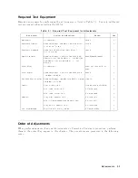
Page 343: ...rope Agilent Technologies Test Measurement European Marketing Organization P O Box 999 1180 AZ Amstelveen The Netherlands tel 31 20 547 9999 Japan Agilent Technologies Japan Ltd Call Center 9 1 Takakura Cho Hachioji Shi Tokyo 192 8510 Japan tel 81 426 56 7832 fax 81 426 56 7840 Latin America Agilent Technologies Latin American Region Headquarters 5200 Blue Lagoon Drive Suite 950 Miami Florida 3312...

Reviews: