6
Troubleshooting
INTRODUCTION
This
c
hapter
describ es
troublesho
oting
o
w
and
pro
vides
the
pro cedure
to
determine
whic
h
group
or
an
assem
bly
is
faulty
and
should
b e
c
hec
k
ed.
TROUBLESHOOTING
SUMMARY
The
troublesho
oting
strategy
of
this
man
ual
is
based
on
a
v
erication
(rather
than
symptomatic)
approac
h.
This
c
hapter
describ es
t
ypical
troublesho
oting
pro cedure
step
b
y
step
and
y
ou
can
iden
tify
a
faulty
assem
bly
or
a
faulty
group
b
y
follo
wing
the
troblesho
oting
steps
sequen
tially
.
And
if
y
ou
could
iden
tify
only
the
faulty
group,
refer
to
the
appropriate
c
hapter
following
this
c
hapter.
Eac
h
of
following
three
c
hapters
v
eries,
one
at
a
time,
the
assem
blies
within
a
group
un
til
the
faulty
assem
bly
is
iden
tied.
These
c
hapters
emplo
y
more
length
y
,
complicated
pro cedures.
The
three
functional
groups
are
p o
w
er
supply
,
digital
con
trol
and
accessories.
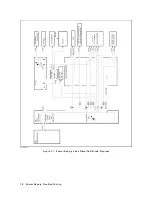
Figure
6-1
diagrams
the
troublesho
oting
organization.
Post-R
ep
air
Pr
o
c
e
dur
es
,
is
the
last
c
hapter
of
the
troublesho
oting
p ortion
of
the
man
ual.
Post-R
ep
air
Pr
o
c
e
dur
es
is
organized
b
y
assem
bly
and
notes
what
adjustmen
t
to
p erform
and
ho
w
to
v
erify
prop er
instrumen
t
op eration
following
the
replacemen
t
of
an
assem
bly
.
Troubleshooting
6-1
Summary of Contents for 4395A
Page 10: ......
Page 26: ......
Page 34: ......
Page 77: ...Figure 2 17 B R Magnitude Ratio Phase Dynamic Accuracy Test Setup 2 Performance Tests 2 43 ...
Page 167: ...Figure 5 1 Adjustment Hardware Setup Adjustments 5 5 ...
Page 186: ...Figure 5 13 Receiver Gain Adjustment Location 5 24 Adjustments ...
Page 190: ...Figure 5 16 Receiver Flatness Adjustment Setup 1 MHz 5 28 Adjustments ...
Page 194: ...Figure 5 20 DC Bias Adjustment Setup 2 5 32 Adjustments ...
Page 196: ...Figure 6 1 Troubleshooting Organization 6 2 Troubleshooting ...
Page 206: ...Figure 7 1 Power Supply Lines Simplified Block Diagram 7 2 Power Supply Troubleshooting ...
Page 212: ...Figure 7 5 A1 CPU Connector Locations 7 8 Power Supply Troubleshooting ...
Page 220: ...Figure 8 1 Digital Control Group Simplified Block Diagram 8 2 Digital Control Troubleshooting ...
Page 240: ...Figure 10 1 Top View Major Assemblies 10 4 Replaceable Parts ...
Page 292: ...Table A 2 Manual Changes by Firmware Version Version Make Manual Changes A 2 Manual Changes ...
Page 308: ......
Page 311: ...Figure B 1 Power Cable Supplied Power Requirement B 3 ...
Page 312: ......
Page 342: ......


