A
Manual
Changes
Introduction
This
app endix
con
tains
the
information
required
to
adapt
this
man
ual
to
earlier
v
ersions
or
congurations
of
the
analyzer
than
the
curren
t
prin
ting
date
of
this
man
ual.
The
information
in
this
man
ual
applies
directly
to
the
4395A
Net
w
ork/Sp ectrum/Imp edance
Analyzer
serial
n
um
b er
prex
listed
on
the
title
page
of
this
man
ual.
Manual
Changes
T
o
adapt
this
man
ual
to
y
our
4395A,
see
T
able
A-1
and
T
able
A-2,
and
make
all
the
man
ual
c
hanges
listed
opp osite
y
our
instrumen
t's
serial
n
um
b er
and
rm
w
are
v
ersion.
Instrumen
ts
man
ufactured
after
the
prin
ting
of
this
man
ual
may
b e
dieren
t
from
those
do cumen
ted
in
this
man
ual.
Later
instrumen
t
v
ersions
will
b e
do cumen
ted
in
a
man
ual
c
hanges
supplemen
t
that
will
accompan
y
the
man
ual
shipp ed
with
that
instrumen
t.
If
y
our
instrumen
t's
serial
n
um
b er
is
not
listed
on
the
title
page
of
this
man
ual
or
in
T
able
A-1,
it
may
b e
do cumen
ted
in
a
yel
low
MANUAL
CHANGES
supplemen
t.
In
additions
to
c
hange
information,
the
supplemen
t
may
con
tain
information
for
correcting
errors
(Errata)
in
the
man
ual.
T
o
k
eep
this
man
ual
as
curren
t
and
accurate
as
p ossible,
Agilent
T
ec
hnologies
recommends
that
y
ou
p erio
dically
request
the
latest
MANUAL
CHANGES
supplemen
t.
F
or
information
concerning
serial
n
um
b er
prexes
not
listed
on
the
title
page
or
in
the
MANUAL
CHANGE
supplemen
t,
con
tact
the
nearest
Agilent
T
ec
hnologies
oce.
T
urn
on
the
line
switch
or
execute
the
*IDN?
command
b
y
GPIB
to
conrm
the
rm
w
are
v
ersion.
See
the
GPIB
Command
R
efer
enc
e
man
ual
for
information
on
the
*IDN?
command.
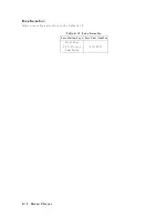
T
able
A-1.
Manual
Changes
b
y
Serial
Number
Serial
Prex
or
Numb er
Mak
e
Man
ual
Changes
JP1KE00275
or
b elo
w
Change
1
JP1KE00413
or
b elo
w
Change
2
JP1KE00536
or
b elo
w
Change
3
JP1KE01646
or
b elo
w
Change
4
from
JP1KE00276
to
JP1KE002173
Change
5
JPIKE02196
or
b elo
w
MY41100219
or
b elo
w
Change
6
Manual
Changes
A-1
Summary of Contents for 4395A
Page 10: ......
Page 26: ......
Page 34: ......
Page 77: ...Figure 2 17 B R Magnitude Ratio Phase Dynamic Accuracy Test Setup 2 Performance Tests 2 43 ...
Page 167: ...Figure 5 1 Adjustment Hardware Setup Adjustments 5 5 ...
Page 186: ...Figure 5 13 Receiver Gain Adjustment Location 5 24 Adjustments ...
Page 190: ...Figure 5 16 Receiver Flatness Adjustment Setup 1 MHz 5 28 Adjustments ...
Page 194: ...Figure 5 20 DC Bias Adjustment Setup 2 5 32 Adjustments ...
Page 196: ...Figure 6 1 Troubleshooting Organization 6 2 Troubleshooting ...
Page 206: ...Figure 7 1 Power Supply Lines Simplified Block Diagram 7 2 Power Supply Troubleshooting ...
Page 212: ...Figure 7 5 A1 CPU Connector Locations 7 8 Power Supply Troubleshooting ...
Page 220: ...Figure 8 1 Digital Control Group Simplified Block Diagram 8 2 Digital Control Troubleshooting ...
Page 240: ...Figure 10 1 Top View Major Assemblies 10 4 Replaceable Parts ...
Page 292: ...Table A 2 Manual Changes by Firmware Version Version Make Manual Changes A 2 Manual Changes ...
Page 308: ......
Page 311: ...Figure B 1 Power Cable Supplied Power Requirement B 3 ...
Page 312: ......
Page 342: ......


