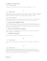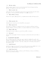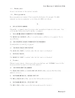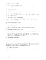
Error
Messages
in
Alphabetical
Order
0160
Blo
c
k
data
error
This
error,
as
w
ell
as
errors
0161
and
0168,
are
generated
when
analyzing
the
syn
tax
of
a
blo
c
k
data
elemen
t.
This
particular
error
message
is
used
if
the
analyzer
cannot
detect
a
more
sp ecic
error.
0168
Blo
c
k
data
not
allow
ed
A
legal
blo
c
k
data
elemen
t
w
as
encoun
tered
but
w
as
not
allo
w
ed
b
y
the
analyzer
at
this
p oint
in
parsing.
C
13
CALIBRA
TION
ABOR
TED
The
calibration
in
progress
w
as
terminated
due
to
a
c
hange
of
the
active
c
hannel
or
stimulus
parameters.
11
CALIBRA
TION
REQUIRED
No
v
alid
calibration
co ecien
ts
w
ere
found
when
y
ou
attempted
to
turn
calibration
on .
126
CAN'T
CHANGE
NUMBER
OF
POINTS
The
n
um
b er
of
p oints
of
the
sp ectrum
analyzer
mo
de
cannot
b e
to
c
hange
man
ually
,
except
in
zero
span.
133
CAN'T
CHANGE
ON
LIST
SWEEP
When
list
sw
eep
is
selected,
the
follo
wing
parameters
are
not
allo w
ed
to
b e
c
hanged:
CENTER,
SP
AN,
ST
AR
T,
STOP
NOP
IFBW
or
RBW
PO
WER
DC
SOUR
CE
Mo
dify
the
list
table
to
c
hange
these
parameters
in
the
list
sw
eep.
97
CAN'T
CHANGE
WHILE
D
A
T
A
MA
TH
ON
The
setting
cannot
b e
c
hanged
when
the
data
math
function
is
used.
99
CAN'T
CHANGE
WHILE
DUAL
CHAN
OFF
The
Cross
c
hannel
cannot
b e
turned
on
when
dual
c
hannel
is
o.
T
urn
on
the
dual
c
hannel
b efore
the
cross
c
hannel
is
turned
on.
82
CAN'T
CHANGE-
ANOTHER
CONTR
OLLER
ON
BUS
The
analyzer
cannot
assume
the
mo
de
of
system
con
troller
un
til
the
active
con
troller
is
remov
ed
from
the
bus
or
relinquishes
the
bus.
See
Pr
o
gr
amming
Manual
.
Messages-2
Summary of Contents for 4395A
Page 10: ......
Page 26: ......
Page 34: ......
Page 77: ...Figure 2 17 B R Magnitude Ratio Phase Dynamic Accuracy Test Setup 2 Performance Tests 2 43 ...
Page 167: ...Figure 5 1 Adjustment Hardware Setup Adjustments 5 5 ...
Page 186: ...Figure 5 13 Receiver Gain Adjustment Location 5 24 Adjustments ...
Page 190: ...Figure 5 16 Receiver Flatness Adjustment Setup 1 MHz 5 28 Adjustments ...
Page 194: ...Figure 5 20 DC Bias Adjustment Setup 2 5 32 Adjustments ...
Page 196: ...Figure 6 1 Troubleshooting Organization 6 2 Troubleshooting ...
Page 206: ...Figure 7 1 Power Supply Lines Simplified Block Diagram 7 2 Power Supply Troubleshooting ...
Page 212: ...Figure 7 5 A1 CPU Connector Locations 7 8 Power Supply Troubleshooting ...
Page 220: ...Figure 8 1 Digital Control Group Simplified Block Diagram 8 2 Digital Control Troubleshooting ...
Page 240: ...Figure 10 1 Top View Major Assemblies 10 4 Replaceable Parts ...
Page 292: ...Table A 2 Manual Changes by Firmware Version Version Make Manual Changes A 2 Manual Changes ...
Page 308: ......
Page 311: ...Figure B 1 Power Cable Supplied Power Requirement B 3 ...
Page 312: ......
Page 342: ......

