Error
Messages
in
Alphabetical
Order
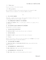
0241
Hardw
are
missing
A
legal
program
command
or
query
could
not
b e
executed
b ecause
of
missing
analyzer
hardw
are.
F
or
example,
an
option
w
as
not
installed.
0111
Header
separator
error
A
c
haracter
that
is
not
a
legal
header
separator
w
as
encoun
tered
while
parsing
the
header.
F
or
example,
no
white
space
follo w
ed
the
header,
th
us
*SRE4
is
an
error.
0114
Header
Sux
out
of
range
The
v
alue
of
a
n
umeric
sux
attac
hed
to
a
program
mnemonic
makes
the
header
in
v
alid.
I
0224
Illegal
parameter
v
alue
Used
where
exact
v
alue,
from
a
list
of
p ossibilities,
w
as
exp ected.
0282
Illegal
program
name
The
name
used
to
reference
a
program
w
as
in
v
alid.
F
or
example,
redening
an
existing
program,
deleting
a
nonexisten
t
program,
or
in
general,
referencing
a
nonexisten
t
program.
0283
Illegal
v
ariable
name
An
attempt
w
as
made
to
reference
a
nonexisten
t
v
ariable
in
a
program.
0213
Init
ignored
A
request
for
a
measuremen
t
initiation
w
as
ignored
as
another
measuremen
t
w
as
already
in
progress.
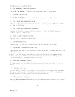
141
INSUFFICIENT
MEMOR
Y
If
a
lot
of
tasks
is
executed
at
same
time,
memory
might
b e
insucien
t
for
a
while.
(F
or
example,
running
HP
Instrumen
t
BASIC
program,
prin
ting
a
screen,
and
sending
or
receiving
data
array
b
y
GPIB
are
required
at
same
time.)
Please
w
ait
un
til
nishing
some
tasks
then
execute
the
next
task.
0161
In
v
alid
blo
c
k
data
A
blo
c
k
data
elemen
t
w
as
exp ected,
but
w
as
in
v
alid
for
some
reason
(see
IEEE
488.2,
7.7.6.2).
F
or
example,
an
END
message
w
as
receiv
ed
b efore
the
length
w
as
satised.
0141
In
v
alid
c
haracter
data
Either
the
c
haracter
data
elemen
t
con
tains
an
in
v
alid
c
haracter
or
the
particular
elemen
t
receiv
ed
is
not
v
alid
for
the
header.
Messages-7
Summary of Contents for 4395A
Page 10: ......
Page 26: ......
Page 34: ......
Page 77: ...Figure 2 17 B R Magnitude Ratio Phase Dynamic Accuracy Test Setup 2 Performance Tests 2 43 ...
Page 167: ...Figure 5 1 Adjustment Hardware Setup Adjustments 5 5 ...
Page 186: ...Figure 5 13 Receiver Gain Adjustment Location 5 24 Adjustments ...
Page 190: ...Figure 5 16 Receiver Flatness Adjustment Setup 1 MHz 5 28 Adjustments ...
Page 194: ...Figure 5 20 DC Bias Adjustment Setup 2 5 32 Adjustments ...
Page 196: ...Figure 6 1 Troubleshooting Organization 6 2 Troubleshooting ...
Page 206: ...Figure 7 1 Power Supply Lines Simplified Block Diagram 7 2 Power Supply Troubleshooting ...
Page 212: ...Figure 7 5 A1 CPU Connector Locations 7 8 Power Supply Troubleshooting ...
Page 220: ...Figure 8 1 Digital Control Group Simplified Block Diagram 8 2 Digital Control Troubleshooting ...
Page 240: ...Figure 10 1 Top View Major Assemblies 10 4 Replaceable Parts ...
Page 292: ...Table A 2 Manual Changes by Firmware Version Version Make Manual Changes A 2 Manual Changes ...
Page 308: ......
Page 311: ...Figure B 1 Power Cable Supplied Power Requirement B 3 ...
Page 312: ......
Page 342: ......


