Error
Messages
in
Alphabetical
Order
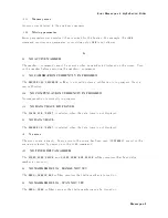
0121
In
v
alid
c
haracter
in
n
um
b er
An
in
v
alid
c
haracter
for
the
data
t
yp e
b eing
parsed
w
as
encoun
tered.
F
or
example,
an
alpha
c
haracter
in
a
decimal
n
umeric
or
a
\9"
in
o ctal
data.
0101
In
v
alid
c
haracter
A
syn
tax
elemen
t
con
tains
a
c
haracter
that
is
in
v
alid
for
that
t
yp e.
F
or
example,
a
header
con
taining
an
amp ersand
( SENSE& ).
154
INV
ALID
D
A
TE
The
date
en
tered
to
set
the
real
time
clo
c
k
is
in
v
alid.
Reen
ter
correct
date.
112
INV
ALID
FILE
NAME
GPIB
only
.
The
le
name
for
the
RECALL,
PUR
GE,
or
RE-SA
VE
function
m
ust
ha
v
e
a
\ _D "
or
\ _S "
extension
for
LIF
format.
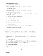
0103
In
v
alid
separator
The
parser
w
as
exp ecting
a
separator
and
encoun
tered
an
illegal
c
haracter.
F
or
example,
the
semicolon
w
as
omitted
after
a
program
message
unit,
*RST:TRIG .
0151
In
v
alid
string
data
A
string
data
elemen
t
w
as
exp ected,
but
w
as
in
v
alid
for
some
reason
(see
IEEE
488.2,
7.7.5.2).
F
or
example,
an
END
message
w
as
receiv
ed
b efore
the
terminal
quote
c
haracter.
0131
In
v
alid
sux
The
sux
do es
not
follo
w
the
syn
tax
describ ed
in
IEEE
488.2,
7.7.3.2,
or
the
sux
is
inappropriate
for
the
analyzer.
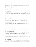
L
115
LIF-DOS
COPY
NOT
ALLO
WED
If
y
ou
try
to
cop
y
a
le
b et
w
een
the
memory
disk
and
the
exible
disk
when
the
format
of
the
memory
disk
is
dieren
t
from
the
format
of
the
exible
disk,
this
message
is
display
ed.
124
LIST
T
ABLE
EMPTY
OR
INSUFFICIENT
T
ABLE
The
frequency
list
is
empt
y
.
T
o
implemen
t
the
list
frequency
mo
de,
add
segmen
ts
to
the
list
table.
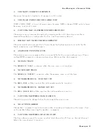
M
0250
Mass
storage
error
Indicates
that
a
mass
storage
error
o ccurred.
This
error
message
is
used
when
the
analyzer
cannot
detect
the
more
sp ecic
errors
describ ed
for
errors
0257.
Messages-8
Summary of Contents for 4395A
Page 10: ......
Page 26: ......
Page 34: ......
Page 77: ...Figure 2 17 B R Magnitude Ratio Phase Dynamic Accuracy Test Setup 2 Performance Tests 2 43 ...
Page 167: ...Figure 5 1 Adjustment Hardware Setup Adjustments 5 5 ...
Page 186: ...Figure 5 13 Receiver Gain Adjustment Location 5 24 Adjustments ...
Page 190: ...Figure 5 16 Receiver Flatness Adjustment Setup 1 MHz 5 28 Adjustments ...
Page 194: ...Figure 5 20 DC Bias Adjustment Setup 2 5 32 Adjustments ...
Page 196: ...Figure 6 1 Troubleshooting Organization 6 2 Troubleshooting ...
Page 206: ...Figure 7 1 Power Supply Lines Simplified Block Diagram 7 2 Power Supply Troubleshooting ...
Page 212: ...Figure 7 5 A1 CPU Connector Locations 7 8 Power Supply Troubleshooting ...
Page 220: ...Figure 8 1 Digital Control Group Simplified Block Diagram 8 2 Digital Control Troubleshooting ...
Page 240: ...Figure 10 1 Top View Major Assemblies 10 4 Replaceable Parts ...
Page 292: ...Table A 2 Manual Changes by Firmware Version Version Make Manual Changes A 2 Manual Changes ...
Page 308: ......
Page 311: ...Figure B 1 Power Cable Supplied Power Requirement B 3 ...
Page 312: ......
Page 342: ......

