Error
Messages
in
Numerical
Order
Error
Messages
in
Numerical
Order
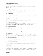
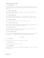
0
-
100
+0
No
error
The
error
queue
is
empt
y
.
Ev
ery
error
in
the
queue
has
b een
read
( OUTPERRO?
query)
or
the
queue
w
as
cleared
b
y
p o
w
er-on
or
the
3 CLS
command.
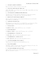
1
CAN'T
SET
RBW
A
UTO
IN
ZERO
SP
AN
The
RBW
A
UTO
mo
de
cannot
b e
selected
in
the
zero
span.
The
RBW
m
ust
b e
sp ecied
man
ually
in
the
zero
span.
(sp ectrum
analyzer
mo
de
only).
10
ADDITIONAL
ST
AND
ARDS
NEEDED
Error
correction
for
the
selected
calibration
class
cannot
b e
computed
un
til
all
the
necessary
standards
ha
v
e
b een
measured.
11
CALIBRA
TION
REQUIRED
No
v
alid
calibration
co ecien
ts
w
ere
found
when
y
ou
attempted
to
turn
calibration
on .
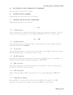
12
NO
CALIBRA
TION
CURRENTL
Y
IN
PROGRESS
The
NNNNNNNNNNNNNNNNNNNNNNNNNNNNNNNNNNNNNNNNNNNNNNNNNNNNNNNNNNN
RESUME
CAL
SEQUENCE
softkey
is
not
v
alid
unless
a
calibration
is
in
progress.
Start
a
new
calibration.
13
CALIBRA
TION
ABOR
TED
The
calibration
in
progress
w
as
terminated
due
to
a
c
hange
of
the
active
c
hannel
or
stimulus
parameters.
14
NOT
V
ALID
FOR
PRESENT
TEST
SET
The
calibration
requested
is
inconsisten
t
with
the
test
set
presen
t.
This
message
o ccurs
in
the
follo
wing
situations:
A
full
2-p ort
calibration
is
requested
with
a
test
set
other
than
an
S-parameter
test
set.
A
one-path
2-p ort
calibration
is
requested
with
an
S-parameter
test
set
(this
pro cedure
is
t
ypically
used
with
a
transmission/reection
test
set).
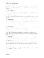
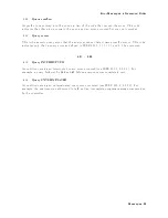
15
EX
CEEDED
7
ST
AND
ARDS
PER
CLASS
A
maximum
of
sev
en
standards
can
b e
dened
for
an
y
class.
16
CURRENT
P
ARAMETER
NOT
IN
CAL
SET
GPIB
only.
Correction
is
not
v
alid
for
the
selected
measuremen
t
parameter.
Messages-16
Summary of Contents for 4395A
Page 10: ......
Page 26: ......
Page 34: ......
Page 77: ...Figure 2 17 B R Magnitude Ratio Phase Dynamic Accuracy Test Setup 2 Performance Tests 2 43 ...
Page 167: ...Figure 5 1 Adjustment Hardware Setup Adjustments 5 5 ...
Page 186: ...Figure 5 13 Receiver Gain Adjustment Location 5 24 Adjustments ...
Page 190: ...Figure 5 16 Receiver Flatness Adjustment Setup 1 MHz 5 28 Adjustments ...
Page 194: ...Figure 5 20 DC Bias Adjustment Setup 2 5 32 Adjustments ...
Page 196: ...Figure 6 1 Troubleshooting Organization 6 2 Troubleshooting ...
Page 206: ...Figure 7 1 Power Supply Lines Simplified Block Diagram 7 2 Power Supply Troubleshooting ...
Page 212: ...Figure 7 5 A1 CPU Connector Locations 7 8 Power Supply Troubleshooting ...
Page 220: ...Figure 8 1 Digital Control Group Simplified Block Diagram 8 2 Digital Control Troubleshooting ...
Page 240: ...Figure 10 1 Top View Major Assemblies 10 4 Replaceable Parts ...
Page 292: ...Table A 2 Manual Changes by Firmware Version Version Make Manual Changes A 2 Manual Changes ...
Page 308: ......
Page 311: ...Figure B 1 Power Cable Supplied Power Requirement B 3 ...
Page 312: ......
Page 342: ......


