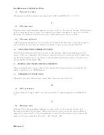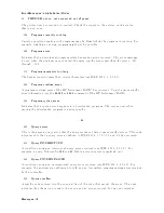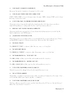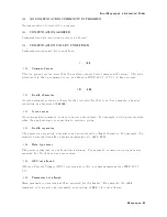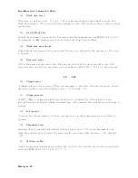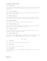
Error
Messages
in
Numerical
Order
100
NO
FIXED
DEL
T
A
MARKER
The
NNNNNNNNNNNNNNNNNNNNNNNNNNNNNNNNNNNNNNNNNNNNNNNNNN
FIXED
1MKR
VALUE
and
NNNNNNNNNNNNNNNNNNNNNNNNNNNNNNNNNNNNNNNNNNNNNNNNNNNNNNNNNNNNNN
FIXED
1MKR
AUX
VALUE
softkey
requires
that
xed
delta
marker
is
turned
on .
101
-
200
110
SA
VE
ERR
OR
A
serious
error,
for
example
ph
ysically
damaged
disk
surface,
is
detected
on
sa
ving
a
le.
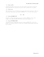
111
RECALL
ERR
OR:
INSTR
ST
A
TE
PRESET
A
serious
error,
for
example
corrupted
data,
is
detected
on
recalling
a
le,
and
this
forced
the
analyzer
to
b e
PRESET.
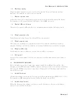
112
INV
ALID
FILE
NAME
GPIB
only
.
The
le
name
for
the
RECALL,
PUR
GE,
or
RE-SA
VE
function
m
ust
ha
v
e
a
\ _D "
or
\ _S "
extension
for
LIF
format.
113
NO
ST
A
TE/DA
T
A
FILES
ON
DISK
There
are
no
les
on
the
exible
disk
with
extensions,
\ _D "
or
\ _S "
for
LIF
format,
or
\ STA "
or
\ .DTA "
for
DOS
format.
114
CAN'T
SA
VE
GRAPHICS
WHEN
COPY
IN
PROGRESS
If
y
ou
attempt
to
sa
v
e
graphics
when
a
prin
t
is
in
progress,
this
error
message
is
display
ed.
115
LIF-DOS
COPY
NOT
ALLO
WED
If
y
ou
try
to
cop
y
a
le
b et
w
een
the
memory
disk
and
the
exible
disk
when
the
format
of
the
memory
disk
is
dieren
t
from
the
format
of
the
exible
disk,
this
message
is
display
ed.
116
NO
ST
A
TE/DA
T
A
FILES
ON
MEMOR
Y
There
are
no
les
on
the
memory
disk
with
extensions,
\ _D "
or
\ _S "
for
LIF
format,
or
\ .STA "
or
\ .DTA "
for
DOS
format.
117
DUPLICA
TE
FILE
EXTENSION
The
extension
name
en
tered
is
already
used
for
other
le
t
yp es.
Use
other
extension
name.
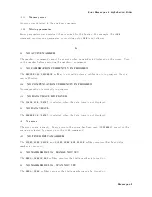
119
NO
D
A
T
A
TRACE
DISPLA
YED
The
NNNNNNNNNNNNNNNNNNNNNNNNNNNNNNNNNNNNNNNNNNNNNNNNNN
SCALE
FOR
[DATA]
is
selected
when
the
data
trace
is
not
display
ed.
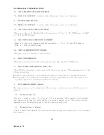
120
NO
MEMOR
Y
TRACE
DISPLA
YED
The
NNNNNNNNNNNNNNNNNNNNNNNNNNNNNNNNNNNNNNNNNNNNNNNNNNNNNNNN
SCALE
FOR
[MEMORY]
is
selected
when
the
memory
trace
is
not
display
ed.
Messages-20
Summary of Contents for 4395A
Page 10: ......
Page 26: ......
Page 34: ......
Page 77: ...Figure 2 17 B R Magnitude Ratio Phase Dynamic Accuracy Test Setup 2 Performance Tests 2 43 ...
Page 167: ...Figure 5 1 Adjustment Hardware Setup Adjustments 5 5 ...
Page 186: ...Figure 5 13 Receiver Gain Adjustment Location 5 24 Adjustments ...
Page 190: ...Figure 5 16 Receiver Flatness Adjustment Setup 1 MHz 5 28 Adjustments ...
Page 194: ...Figure 5 20 DC Bias Adjustment Setup 2 5 32 Adjustments ...
Page 196: ...Figure 6 1 Troubleshooting Organization 6 2 Troubleshooting ...
Page 206: ...Figure 7 1 Power Supply Lines Simplified Block Diagram 7 2 Power Supply Troubleshooting ...
Page 212: ...Figure 7 5 A1 CPU Connector Locations 7 8 Power Supply Troubleshooting ...
Page 220: ...Figure 8 1 Digital Control Group Simplified Block Diagram 8 2 Digital Control Troubleshooting ...
Page 240: ...Figure 10 1 Top View Major Assemblies 10 4 Replaceable Parts ...
Page 292: ...Table A 2 Manual Changes by Firmware Version Version Make Manual Changes A 2 Manual Changes ...
Page 308: ......
Page 311: ...Figure B 1 Power Cable Supplied Power Requirement B 3 ...
Page 312: ......
Page 342: ......

