2
P
erformance
T
ests
INTRODUCTION
This
c
hapter
con
tains
the
p erformance
test
pro cedures.
The
test
pro cedures
listed
in
T
able
1-1
are
describ ed
sequen
tially
in
the
follo wing
pages.
The
test
name
indicates
the
tested
p erformance
and
to
whic
h
p erformance
group
the
tested
p erformance
b elongs
to.
NA
indicates
the
p erformance
test
b elongs
to
the
net
w
ork
analyzer
mo
de
p erformance
group.
SA
indicates
the
p erformance
test
b elongs
to
the
sp ectrum
analyzer
mo
de
p erformance
group.
Eac
h
pro cedure
consists
of
the
following
parts:
Description:
describ es
the
test
pro cedure.
Sp ecication:
describ es
the
p erformance
v
eried
in
the
test.
T
est
Equipmen
t:
describ es
test
equipmen
t
required
in
the
test.
Pro cedure:
describ es
the
test
pro cedure
step
b
y
step.
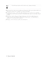
Note
Allow
the
analyzer
to
w
arm
up
for
at
least
30
min
utes
b efore
y
ou
execute
an
y
of
the
p erformance
tests.
P
erform
all
p erformance
tests
in
an
ambien
t
temp erature
of
23
6
5
C.
Note
Before
p erforming
an
y
tests,
make
extra
copies
of
the
calculation
sheet
in
Chapter
3
and
the
p erformance
test
record
in
Chapter
4.
These
are
required
in
the
test
pro cedure.
F
or
an
explanation
of
ho
w
to
use
these
records,
see
the
CALCULA
TION
SHEET
AND
PERFORMANCE
TEST
RECORD
in
Chapter
1.
P
erformance
T
ests
2-1
Summary of Contents for 4395A
Page 10: ......
Page 26: ......
Page 34: ......
Page 77: ...Figure 2 17 B R Magnitude Ratio Phase Dynamic Accuracy Test Setup 2 Performance Tests 2 43 ...
Page 167: ...Figure 5 1 Adjustment Hardware Setup Adjustments 5 5 ...
Page 186: ...Figure 5 13 Receiver Gain Adjustment Location 5 24 Adjustments ...
Page 190: ...Figure 5 16 Receiver Flatness Adjustment Setup 1 MHz 5 28 Adjustments ...
Page 194: ...Figure 5 20 DC Bias Adjustment Setup 2 5 32 Adjustments ...
Page 196: ...Figure 6 1 Troubleshooting Organization 6 2 Troubleshooting ...
Page 206: ...Figure 7 1 Power Supply Lines Simplified Block Diagram 7 2 Power Supply Troubleshooting ...
Page 212: ...Figure 7 5 A1 CPU Connector Locations 7 8 Power Supply Troubleshooting ...
Page 220: ...Figure 8 1 Digital Control Group Simplified Block Diagram 8 2 Digital Control Troubleshooting ...
Page 240: ...Figure 10 1 Top View Major Assemblies 10 4 Replaceable Parts ...
Page 292: ...Table A 2 Manual Changes by Firmware Version Version Make Manual Changes A 2 Manual Changes ...
Page 308: ......
Page 311: ...Figure B 1 Power Cable Supplied Power Requirement B 3 ...
Page 312: ......
Page 342: ......


