Chapter 6 Specifications
Introduction
6-6
Assembly Level Service Guide
6
General information (continued)
53147A, 53148A, and 53149A
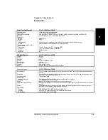
Power Supply
ac
Line selection
Power requirements
dc (Option 002 only)
Battery (Option 002)
Type
Charge Time
Capacity
Size
Operating temperature
Weight (nominal)
Safety
EMC
Accessories
Supplied
Available
Power sensors
Spare battery
DC power input cable
90-132 Vac; 47.5-66 Hz or 360-440 Hz
216-264 Vac; 47.5-66 Hz
automatic
80 VA max. (32 W typical)
11-18 Vdc; 2A max.
VHS camcorder, lead acid (2 each)
8 hours in unit (typical)
2 hours min. at 25° C
330 mm W x 156 mm H x 376 mm D with bumpers and handles. Rack panel is full EIA width and 3U ISO height.
0-55° C, 0-40° C with battery option
4.5 kg without battery option, 6.6 kg with battery option
Designed in compliance with IEC-1010, CAN/CSA 1010.1
Designed in compliance with IEC-11, EN50082-1, IEC801-2, -3, -4
Power sensor cable (11730A); DVM test leads (34132B); operating/programming and service manuals; ac power
cord
8480 series (see table below)
53150-80010
53150-60214
Available sensors
Frequency Range
Connector
Zero Set
25 Watt sensors
1 mW to 25 W
(0 to +44 dBm)
8481B
8482B
3 Watt sensors
100 µ W to 3 W
(-10 to +35 dBm)
8481H
8482H
100 mW sensors
1 µ W to 100 mW
(-30 to +20 dBm)
8485A
8485A Option 033
8481A
8482A
8487A
High sensitivity sensors
100 pW to 10 µ W
(-70 to -20 dBm)
8481D
8485D
8485D Option 033
8487D
10 MHz to 18 GHz
100 kHz to 4.2 GHz
10 MHz to 18 GHz
100 kHz to 4.2 GHz
50 MHz to 26.5 GHz
50 MHz to 33 GHz
10 MHz to 18 GHz
100 kHz to 4.2 GHz
50 MHz to 50 GHz
10 MHz to 18 GHz
50 MHz to 26.5 GHz
50 MHz to 33 GHz
50 MHz to 50 GHz
N (m)
N (m)
N (m)
N (m)
APC-3.5 mm (m)
APC-3.5 mm (m)
N (m)
N (m)
2.4 mm (m)
N (m)
APC-3.5 mm (m)
APC-3.5 mm (m)
2.4 mm (m)
±50 µ W
±50 µ W
±5 µ W
±5 µ W
±50 nW
±50 nW
±50 nW
±50 nW
±50 nW
±20 pW
±20 pW
±20 pW
±20 pW
Summary of Contents for 53147A
Page 6: ...Contents vi Assembly Level Service Guide ...
Page 13: ...1 Performance Tests Verifying Specifications ...
Page 55: ...2 Service ...
Page 88: ...Chapter 2 Service Troubleshooting the Instrument 2 34 Assembly Level Service Guide 2 ...
Page 89: ...3 Replacing Assemblies Disassembly and Reassembly ...
Page 104: ...Chapter 3 Replacing Assemblies Removing the Power Supply 3 16 Assembly Level Service Guide 3 ...
Page 105: ...4 Replaceable Parts ...
Page 116: ...Chapter 4 Replaceable Parts Parts Identification 4 12 Assembly Level Service Guide 4 ...
Page 117: ...5 Backdating ...
Page 119: ...6 Specifications ...
Page 125: ...A Rack Mounting the Instrument ...
Page 134: ...Index Index 4 Assembly Level Service Guide Index ...

