Chapter 1 Performance Tests
Operational Verification
1-12
Assembly Level Service Guide
1
12
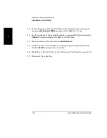
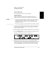
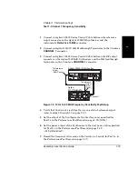
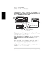
Set the frequency of the first Synthesizer (connected to the instrument’s
rear-panel
Reference 10MHz
connector) to 10 MHz at 1 V rms.
13
Set the frequency of the second Synthesizer (connected to the instrument’s
Channel 1
input connector) to 2 MHz at 100 mV rms.
14
Press and release the instrument’s
Reset/Local
key.
15
Verify that the Counter displays a reading of approximately 2 MHz and
that the
Ext Ref
annunciator is activated.
16
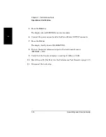
Mark Pass or Fail for Test 4 in the Performance Test Record on page 1-39.
17
Disconnect the test setup.
Summary of Contents for 53147A
Page 6: ...Contents vi Assembly Level Service Guide ...
Page 13: ...1 Performance Tests Verifying Specifications ...
Page 55: ...2 Service ...
Page 88: ...Chapter 2 Service Troubleshooting the Instrument 2 34 Assembly Level Service Guide 2 ...
Page 89: ...3 Replacing Assemblies Disassembly and Reassembly ...
Page 104: ...Chapter 3 Replacing Assemblies Removing the Power Supply 3 16 Assembly Level Service Guide 3 ...
Page 105: ...4 Replaceable Parts ...
Page 116: ...Chapter 4 Replaceable Parts Parts Identification 4 12 Assembly Level Service Guide 4 ...
Page 117: ...5 Backdating ...
Page 119: ...6 Specifications ...
Page 125: ...A Rack Mounting the Instrument ...
Page 134: ...Index Index 4 Assembly Level Service Guide Index ...


