Chapter 1 Performance Tests
Operational Verification
1-16
Assembly Level Service Guide
1
5
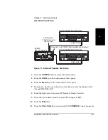
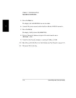
Observe and record the voltage reading on the Agilent 34401A Multimeter.
6
Disconnect the test leads from the Agilent E3640A DC Power Supply.
Be careful not to disturb the voltage setting.
7
Connect the test leads to the Agilent 53147A/48A/49A (be sure to observe
the correct polarity).
8
Press the
Display DVM
key on the Agilent 53147A/48A/49A front panel.
9
Connect the test prods to the output terminals on the Agilent E3640A
DC Power Supply (be sure to observe the correct polarity).
10
Observe and record the voltage reading on the Agilent 53147A/48A/49A.
11
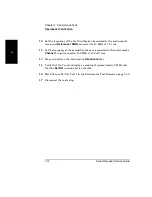
Compare the voltage readings you recorded in steps 5 and 10. If the
reading taken with the Agilent 53147A/48A/49A is within ±0.25% ±10 mV
of the reading taken with the Agilent 34401A, mark Pass for Test 6 in the
Performance Test Record on page 1-39. If the reading taken with the
Agilent 53147A/48A/49A is not within ±0.25% ±10 mV of the reading
taken with the Agilent 34401A, mark Fail for Test 6 in the Performance
Test Record on page 1-39.
This completes the Operational Verification.
Summary of Contents for 53147A
Page 6: ...Contents vi Assembly Level Service Guide ...
Page 13: ...1 Performance Tests Verifying Specifications ...
Page 55: ...2 Service ...
Page 88: ...Chapter 2 Service Troubleshooting the Instrument 2 34 Assembly Level Service Guide 2 ...
Page 89: ...3 Replacing Assemblies Disassembly and Reassembly ...
Page 104: ...Chapter 3 Replacing Assemblies Removing the Power Supply 3 16 Assembly Level Service Guide 3 ...
Page 105: ...4 Replaceable Parts ...
Page 116: ...Chapter 4 Replaceable Parts Parts Identification 4 12 Assembly Level Service Guide 4 ...
Page 117: ...5 Backdating ...
Page 119: ...6 Specifications ...
Page 125: ...A Rack Mounting the Instrument ...
Page 134: ...Index Index 4 Assembly Level Service Guide Index ...

