background image

Chapter 2  Service

Calibration Procedures

Assembly Level Service Guide

2-11

2

5

Turn on the Agilent 53147A/48A/49A and then wait for at least 
30 minutes to allow the internal temperature of the instrument 
to stabilize.

6

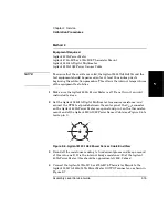
Connect an Agilent E9635A adapter to the Power Meter 

OUTPUT

 connector 

as shown in Figure 2-2.

7

Connect an Agilent 10503 series cable from the Agilent E9635A adapter 
on the Agilent 53147A/148A/149A’s Power Meter 

OUTPUT

 connector to 

the 

CHANNEL 1

 input connector on the Agilent 53150A/51A/52A 

Frequency Counter.

8

Set the Agilent 53150A/51A/52A Frequency Counter to measure frequency 
on Channel 1.

9

Turn on the Agilent 53147A/148A/149A’s internal power reference oscillator:

Press 

Shift

 + 

Menu

, use the up and/or down arrow keys to cycle through 

the menu to 

PWR REF

, press the right-arrow key, then use the up or down 

arrow key to change the setting to 

ON

, and press the 

Enter

 key. The 

Pwr Ref

 annunciator should now be activated.

NOTE

The reference oscillator is normally off. It is turned on automatically 
during calibration and then turned back off when calibration is complete. 
Setting 

PWR REF

 in the 53147A/148A/149A’s menu to 

ON

 turns the power 

reference oscillator on, and it remains on until the 

PWR REF

 menu setting 

is returned to 

OFF

. When you calibrate the Power Meter with 

PWR REF


set to 

ON

, the power reference oscillator remains on after calibration is 

complete.

10

Insert a small, non-conductive, slot-type adjustment tool into the hole 
in the side of the power reference oscillator shield (see Figure 2-3)
This opening allows access to L9, the adjustable inductor that is used to 
adjust the frequency of the power reference oscillator.

Summary of Contents for 53147A

Page 1: ...is guide describes how to service the Agilent 53147A 53148A and 53149A The information in this guide applies to instruments having the number prefix listed below unless accompanied by a Manual Updating Changes package indicating otherwise SERIAL PREFIX NUMBER US4047 53147A US4048 53148A US4049 53149A ...

Page 2: ...ent will replace software media which does not execute its programming instructions due to such defects For detailed warranty information see back matter Safety Considerations General This product and related documentation must be reviewed for familiarization with this safety markings and instructions before operation Before Cleaning Disconnect the product from operating power before cleaning Warn...

Page 3: ...sitivity 1 18 Test 1b 50 MHz to 125 MHz Frequency Sensitivity 1 20 Test 2 Channel 2 Frequency Sensitivity 1 23 Test 2a 50 MHz to 20 GHz Frequency Sensitivity 1 23 Test 2b 22 GHz to 26 5 GHz Frequency Sensitivity 1 25 Test 2c 30 GHz to 46 GHz Frequency Sensitivity 1 26 Test 3 Power Measurement 1 27 Power Measurement Accuracy Test 1 27 Test 4 Power Reference Oscillator Frequency 1 30 Power Reference...

Page 4: ...requency Calibration 2 9 Power Reference Oscillator Level Adjustment 2 13 DVM Calibration 2 20 Pre Troubleshooting Information 2 23 Safety Considerations 2 23 Recommended Test Equipment 2 24 Repair Considerations 2 24 Electrostatic Discharge 2 24 Surface Mount Repair 2 25 Disassembly and Reassembly Specifics 2 25 After Service Considerations 2 25 Product Safety Checks 2 25 Product Performance Chec...

Page 5: ...r Panel Assembly 3 11 Removing the Cooling Fan 3 14 Removing the Power Supply 3 15 4 Replaceable Parts Introduction 4 2 Replaceable Parts 4 2 How To Order A Part 4 3 Contacting Agilent Technologies 4 4 Parts Identification 4 5 Reference Designations 4 5 Cabinet Parts and Hardware 4 5 Accessories and Miscellaneous Items 4 5 5 Backdating Introduction 5 2 6 Specifications Introduction 6 2 Measurement...

Page 6: ...Contents vi Assembly Level Service Guide ...

Page 7: ...alibration Service is available for Agilent customers in the USA If downtime is critical you can receive your repaired instrument via overnight shipment Call 800 403 0801 and ask for Emergency Response or Express Calibration Service When your instrument is repaired it is returned via overnight shipment at no extra charge If you decide to service the instrument yourself use the troubleshooting proc...

Page 8: ...higher serial prefix are covered when required by one or more manual change sheets included with this guide If a required change sheet is missing contact your nearest Agilent Sales Office listed at the back of this guide Assembly Level Service Guide Organization This Assembly Level Service Guide consists of a table of contents a preface six chapters and an index The page headers identify the chapt...

Page 9: ...er 5 Backdating contains information required to adapt this manual for older instruments to be provided when required Chapter 6 Specifications lists all the specifications and operating characteristics for the Agilent 53147A 148A 149A How to Order Guides The part number for this guide is listed on the Certification and Warranty page on the back of the title page and on the back cover of this guide...

Page 10: ... 148A 149A include Frequency Relative Frequency Frequency Offset and Power including Power Offset and Relative Power All of these features are accessible from the front panel and over the GPIB and RS 232 interfaces The Agilent 53147A 148A 149A includes the following additional measurement functions and features that are designed specifically for manufacturing and service applications 1 2 5 and 10 ...

Page 11: ...ptions ordered with the instrument are installed at the factory and are ready for operation on delivery Hardware High Stability Oven Timebase Option 001 Battery DC Power Input Option 002 Rack Mount Kit Option 1CM Soft Carrying Case Option 007 Retrofit Options 001 and 002 can be installed only by authorized Agilent Technologies Repair Centers Instructions for installing the Rack Mount Kit are provi...

Page 12: ... 34132B Accessories Available Soft Carrying Case Agilent P N 53147 80016 Automotive Power Adapter Agilent P N 53150 60214 Battery Agilent P N 53150 80010 GPIB Cables Agilent P N 10833A B C D RS 232 Cable Agilent P N 53150 60215 Power Sensors Agilent 8480 series Manuals Supplied Agilent 53147A 148A 149A Operating and Programming Guide Agilent P N 53147 90009 Agilent 53147A 148A 149A Assembly Level ...

Page 13: ...1 Performance Tests Verifying Specifications ...

Page 14: ...erformance Tests This chapter is organized as follows Introduction pg 1 2 Equipment Required pg 1 4 Operational Verification pg 1 6 Complete Performance Tests pg 1 17 Performance Test Record pg 1 39 Operational Verification Operational Verification is an abbreviated series of tests that you can perform instead of performing the Complete Performance Tests to provide a high degree of confidence that...

Page 15: ...e type of use environmental conditions aging and measurement accuracy required the instrument should be checked using the operational verification procedure at least once every year A full Calibration and Performance Test should be performed each time the instrument changes environment or if an assembly or module has been replaced Test Record The results of the Operational Verification and the Com...

Page 16: ... E3640A 1 OV Frequency Counter 10 Hz to 125 MHz Agilent 53150A 51A 52A 1 P C T Power Meter Range 1 mW Agilent 432A 1 P C T Power Meter 50 MHz to 50 GHz 13 dBm to 50 dBm Agilent 437B 1 P C T Power Meter 100 kHz to 110 GHz 70 dBm to 44 dBm Agilent E4418B 1 P C T Thermistor Mount SWR 1 05 at 50 MHz Accuracy 0 5 at 50 MHz Agilent 478A H75 or 478A H76 1 P T Power Sensor 10 MHz to 18 GHz 30 dBm to 20 dB...

Page 17: ...t 11667C D 1 P T Cables BNC m to BNC m 2 4 mm m to 2 4 mm m Agilent 10503 series 2 OV P C T Adapters BNC f to Type N m BNC m to SMA f 3 5 mm f to 2 92 mm m 2 92 mm m to 2 4 mm m 2 92 mm m to 2 4 mm f 2 4 mm m to 2 4 mm m 2 4 mm f to 2 4 mm f Agilent E9635A Agilent 1250 2015 Agilent 11904A Agilent 11904D Agilent 11900A Agilent 11900B 1 1 1 1 1 1 1 P C T Equivalent equipment can be substituted for a...

Page 18: ...r are written so that little experience is necessary These procedures should be followed in the order in which they appear Power On Self Tests NOTE This test is appropriate for the Agilent 53147A 53148A and 53149A 1 Inspect the instrument for damage 2 Make sure no cables are connected to the instrument s inputs 3 Connect the power cord to the instrument and the power source NOTES Since the instrum...

Page 19: ...ex number is also displayed GPIB ADDR nn nn a two digit number from 0 to 30 is displayed CH2 NO SIGNAL is displayed 6 If an error message is displayed refer to the troubleshooting section in Chapter 2 Service 7 Mark Pass or Fail in the Performance Test Record on page 1 39 Test 1 NOTE To ensure that the test results are valid the instrument and the test equipment should be powered on for at least 3...

Page 20: ... Reference 10MHz connector on the instrument s rear panel to the CHANNEL 1 input connector on the front panel 2 Press and release the Chan Select key 3 Verify that Ch 1 is displayed in the upper left corner of the display 4 Verify that the display reads 10 000 000 Hz 5 Mark Pass or Fail in the Performance Test Record on page 1 39 Test 2 ...

Page 21: ...release the Shift key and then press and release the Menu Reset Local key 3 Press the up and or down arrow key s as many times as necessary until DO SELF TEST is displayed 4 Press and release the Enter key 5 If no errors are detected SELF TEST OK is briefly displayed when the self test is completed If any error messages are displayed refer to the troubleshooting section in Chapter 2 Service 6 Mark...

Page 22: ...nstrument and the test equipment should be powered on for at least 30 minutes prior to beginning the tests This allows the internal temperatures of the equipment to stabilize These tests are appropriate for the Agilent 53147A 53148A and 53149A 1 Connect an Agilent 10503 series coaxial cable between the output of the first Agilent 3325A B Synthesizer and the Reference 10MHz connector on the instrum...

Page 23: ...y use the up and down arrow keys to cycle the display until it reads REF OSC INT 8 Press the right arrow key once INT begins to flash off and on 9 Press the up or down arrow key once INT changes to EXT 10 Press the Enter key 11 Press the Chan Select key once to select the CHANNEL 1 input connector Agilent Agilent 53147A 48A 49A Agilent 3325A B Synthesizer Agilent 3325A B Synthesizer To Reference 1...

Page 24: ...z at 1 V rms 13 Set the frequency of the second Synthesizer connected to the instrument s Channel 1 input connector to 2 MHz at 100 mV rms 14 Press and release the instrument s Reset Local key 15 Verify that the Counter displays a reading of approximately 2 MHz and that the Ext Ref annunciator is activated 16 Mark Pass or Fail for Test 4 in the Performance Test Record on page 1 39 17 Disconnect th...

Page 25: ...s are appropriate for the Agilent 53147A 53148A and 53149A 1 Connect one end of the Agilent 11730A cable supplied with instrument to the Power Meter INPUT connector on the front panel of the Agilent 53147A 53148A or 53149A 2 Connect the other end of the Agilent 11730A cable to a power sensor head 3 Press the Display Power key in the Power Meter area of the front panel The display should look like ...

Page 26: ...onnect the power sensor head to the Power Meter OUTPUT connector 7 Press the Cal key The display briefly shows CALIBRATING 8 Turn on the power reference output in the instrument s menu PWR REF ON 9 Verify that the Counter displays a reading of 0 dBm 02 dB 10 Mark Pass or Fail for Test 5 in the Performance Test Record on page 1 39 11 Disconnect the test setup ...

Page 27: ...res of the equipment to stabilize These tests are appropriate for the Agilent 53147A 53148A and 53149A 1 Set the output of the E3640A DC Power Supply to 25 VDC 2 Set the Agilent 34401A Digital Multimeter to the lowest DC voltage range capable of safely measuring 25 VDC 3 Connect the test leads to the Multimeter observe correct polarity 4 Connect the test prods to the output terminals on the Agilen...

Page 28: ...t prods to the output terminals on the Agilent E3640A DC Power Supply be sure to observe the correct polarity 10 Observe and record the voltage reading on the Agilent 53147A 48A 49A 11 Compare the voltage readings you recorded in steps 5 and 10 If the reading taken with the Agilent 53147A 48A 49A is within 0 25 10 mV of the reading taken with the Agilent 34401A mark Pass for Test 6 in the Performa...

Page 29: ...he test equipment should be powered on for at least 30 minutes prior to beginning the tests This allows the internal temperatures of the equipment and the timebase to stabilize NOTE Other instrument measurement functions e g Averaging are mathematically derived by the microprocessor from the parameters verified by these performance tests If the instrument passes the performance tests the other mea...

Page 30: ...11904A 2 92 mm m to 2 4 mm m Adapter Agilent 10100C 50 Ω Feedthrough Terminator Agilent 10503 Series Coaxial Cable BNC m to m 2 mm m to 2 mm f Cable 2 Test 1a 10 Hz to 20 MHz Frequency Sensitivity NOTES To ensure that the test results are valid the instrument and the test equipment should be powered on for at least 30 minutes prior to beginning the tests This allows the internal temperatures of th...

Page 31: ...r s CHANNEL 1 connector Figure 1 3 10 Hz to 20 MHz Frequency Sensitivity Test Setup 4 Verify that the Counter is still set to use an external reference signal refer to steps 5 through 10 on page 1 11 5 Set the output of the Synthesizer to the first frequency specified for Test 1a in the Performance Test Record on page 1 39 10 Hz 6 Set the power output of the Synthesizer to the first power value sp...

Page 32: ...t Do not turn off the instrument Turning the instrument off and back on resets the reference oscillator REF OSC selection to internal INT and the channel selection to CHANNEL 2 Test 1b 50 MHz to 125 MHz Frequency Sensitivity 1 Connect an Agilent 10100C 50 Ω Feedthrough Terminator to the CHANNEL 1 input connector on the instrument s front panel refer to Figure 1 4 for steps 1 through 9 Figure 1 4 5...

Page 33: ... the Adapter on the Synthesizer s RF output connector and the input connector on the Agilent 11667C Power Splitter 8 Connect the Agilent 8487A D Power Sensor to the remaining output connector on the Agilent 11667C Power Splitter 9 Connect the Agilent 11730A Power Sensor Cable between the Power Sensor and the sensor connector on the Agilent 437B Power Meter 10 Verify that the Counter is still set t...

Page 34: ... Pass in the Performance Test Record for Test 1b If either of the frequency readings you recorded are incorrect mark Fail in the Performance Test Record 16 Disconnect the Agilent 10100C Feedthrough Terminator the Agilent 1250 2015 Adapter and the Agilent 11904A Adapter from the Counter s CHANNEL 1 connector NOTES Do not disconnect the rest of the test setup as these connections are also used in th...

Page 35: ...le 2 Test 2a 50 MHz to 20 GHz Frequency Sensitivity NOTES To ensure that the test results are valid the instrument and the test equipment should be powered on for at least 30 minutes prior to beginning the tests This allows the internal temperatures of the equipment to stabilize This test is appropriate for the Agilent 53147A 53148A and 53149A 1 Connect the Agilent 11904D 2 92 mm m to 2 4 mm f Ada...

Page 36: ...first frequency specified for Test 2a in the Performance Test Record on page 1 40 50 MHz 7 Set the power output of the Synthesizer read on the Power Meter to a power value 20 dBm above the value specified for Test 2a in the Performance Test Record on page 1 40 0 dBm The added 20 dBm compensates for the 20 dB Attenuator 8 Record the frequency value read on the Counter 1 count for Test 2a in the Per...

Page 37: ...se the same test setup as described for Test 2a on page 1 23 2 Set the output of the Agilent 83650B Synthesizer to the first frequency specified for Test 2b in the Performance Test Record on page 1 40 22 GHz 3 Set the power output of the Synthesizer read on the Power Meter to a power value 20 dBm above the value specified for Test 2b in the Performance Test Record on page 1 40 5 dBm for the Agilen...

Page 38: ...s for the 20 dB Attenuator 4 Record the frequency value read on the Counter 1 count for Test 2c in the Performance Test Record on page 1 40 5 Repeat steps 2 through 4 for each of the remaining frequencies specified for Test 2c Don t forget to change the power level for the 42 44 and 46 GHz tests 6 If all of the frequency values you recorded for Test 2c are correct mark Pass in the Performance Test...

Page 39: ... instrument and the test equipment should be powered on for at least 30 minutes prior to beginning the tests This allows the internal temperatures of the equipment to stabilize These tests are appropriate for the Agilent 53147A 53148A and 53149A 1 Connect the Agilent 11730A Power Sensor Cable between Agilent 11683A Range Calibrator s output connector and the Agilent 53147A 53148A or 53149A s Power...

Page 40: ...he Agilent 53147A 53148A or 53149A display reads 1 000 0 006 mW NOTE The Range Calibrator output level is adjustable in 5 dB increments Thus the 3 µW 30 µW 300 µW 3 mW and 30 mW legends on the RANGE switch are approximations The true values for these settings are 3 16 µW 31 6 µW 316 µW 3 16 mW and 31 6 mW 9 Set the Range Calibrator RANGE switch to each of the positions shown in Table 1 3 For each ...

Page 41: ...ng in the Performance Test Record 14 Set the Range Calibrator s RANGE switch to 10 dBm 15 Verify that the Power Meter displays a reading of 10 00 0 04 dBm 16 Record the actual power reading in the Performance Test Record 17 Review all of the results for Test 3 and mark Pass or Fail for Test 3 in the Performance Test Record Table 1 3 Range Calibrator Settings and Expected Results Range Calibrator A...

Page 42: ...d on for at least 30 minutes prior to measuring the power reference oscillator output This allows the internal temperatures of the equipment to stabilize This procedure specifies the Agilent 53150A for measuring the frequency output of the 53147A 48A 49A s power reference oscillator If the 53147A 48A 49A s Frequency Counter is known to be in calibration see Test 1 Channel 1 Frequency Sensitivity o...

Page 43: ...scillator on and it remains on until the PWR REF menu setting is returned to OFF When you calibrate the Power Meter with PWR REF set to ON the power reference oscillator remains on after calibration is complete 5 Record the power reading shown on the Agilent 53150A 51A 52A for Test 4 in the Performance Test Record on page 1 41 6 Mark Pass or Fail for Test 4 in the Performance Test Record Agilent C...

Page 44: ...49A and the test equipment should be powered on for at least 30 minutes prior to beginning the tests This allows the internal temperatures of the equipment to stabilize The calibration of the Agilent E4418B Power Meter must be no more than one level removed from NIST National Institute of Standards and Technology If the E4418B Power Meter s calibration is more than one level removed from NIST the ...

Page 45: ...alibrate the E4418B Power Meter 6 Disconnect the Agilent 8481A Power Sensor from the Agilent E4418B Power Meter and immediately connect it to the Power OUTPUT connector on the Agilent 53147A 48A 49A see Figure 1 9 Figure 1 9 Power Meter Reference Level Test Setup 7 Record the power reading shown on the Agilent E4418B Power Meter for Test 5 in the Performance Test Record on page 1 41 8 Mark Pass or...

Page 46: ...e This test is appropriate for the Agilent 53147A 53148A and 53149A 1 Turn the Agilent 432A Power Meter off Do not turn it on until instructed to do so 2 Set the Agilent 34401A Digital Multimeter to measure resistance and connect the DVM test prods between the center pin of the VRF connector on the Agilent 432A Power Meter rear panel and pin 1 on the thermistor mount end of the Agilent 8120 1082 P...

Page 47: ...lent 432A Power Meter 6 Turn on the 432A Power Meter Wait 30 minutes for the Power Meter and the Thermistor Mount to stabilize before proceeding to the next step 7 Set the 432A Power Meter s RANGE switch to Coarse Zero 8 Adjust the COARSE ZERO control on the 432A Power Meter s front panel to obtain a zero reading on the meter 9 Set the 432A Power Meter s RANGE switch to 01 mW 20 dBm 10 Press the F...

Page 48: ...ss than 400 microvolts proceed to step 16 If the reading is 400 microvolts or more press the FINE ZERO toggle switch on the 432A Power Meter s front panel down 16 Observe the reading on the Multimeter round off the reading to the nearest microvolt and keep a record of this value as V0 17 Turn on the Agilent 53147A 148A 149A s internal power reference oscillator Press Shift Menu use the up and or d...

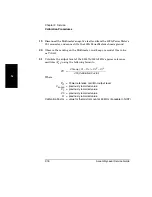
Page 49: ...ing on the Multimeter and keep a record of this value as VCOMP 21 Calculate the output level of the 53147A 148A 149A s power reference oscillator Prf using the following formula Where Prf 2 Vcomp V1 V0 V0 2 V1 2 4R Calibration Factor Prf Power reference oscillator output level Vcomp previously recorded value V1 previously recorded value V0 previously recorded value R previously recorded value Cali...

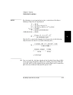
Page 50: ... is very small effectively zero 22 Verify that Prf is between 0 988 mW and 1 012 mW 23 Record the value for Prf in the Performance Test Record on page 1 41 24 Mark Pass or Fail for Test 5 in the Performance Test Record R 200 Ω V0 170 µV or 170 x 10 6 V V1 78 107 µV or 78 107 x 10 6 or 078 V Vcomp 5 1583 V R previously recorded value CalibrationFactor 99 68 Prf 2 Vcomp V1 V0 V0 2 V1 2 4R Calibratio...

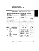
Page 51: ...ests N A 2 10 MHz Test 10 000 000 Hz 3 Run Self Test N A 4 10 MHz External Timebase Input Test 2 MHz 5 Power Meter Test 0 dBm 02 dB 6 DVM Test 25 Vdc 0 25 10 mV 24 365 Vdc to 25 635 Vdc Test Number Complete Performance Tests Specifications Test Results Pass Fail Channel 1 Frequency Sensitivity 1a 10 Hz 30 Hz 1 kHz 500 kHz 5 MHz 10 MHz 20 MHz 10 Hz 40 mV rms 14 9 dBm 30 Hz 40 mV rms 14 9 dBm 1 kHz ...

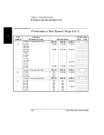
Page 52: ...53148A 53149A 2a 50 MHz 100 MHz 250 MHz 300 MHz 500 MHz 1 GHz 2 5 GHz 5 GHz 10 GHz 12 4 GHz 16 GHz 18 GHz 19 GHz 20 GHz 20 dBm 33 dBm 29 dBm 20 dBm 33 dBm 29 dBm 20 dBm 33 dBm 30 dBm 27 dBm Channel 2 Frequency Sensitivity 53147A 53148A 53149A 2b 22 GHz 24 GHz 26 5 GHz N A N A N A 25 dBm 27 dBm Channel 2 Frequency Sensitivity 53147A 53148A 53149A 2c 30 GHz 34 GHz 40 GHz 42 GHz 44 GHz 46 GHz N A N A...

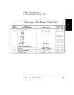
Page 53: ...umber Complete Performance Tests Specifications Test Results Pass Fail Power Measurement 3 3 µW 10 µW 30 µW 100 µW 300 µW 1 mW 3 mW 10 mW 30 mW 100 mW 20 00 dBm 10 00 dBm 0 02 dB or 0 5 0 04 dBm 0 04 dBm 4 Power Reference Frequency 50 0 MHz 1 49 5 MHz to 50 5 MHz 50 0 MHz 5 Power Reference Level 1 0 mW 1 2 0 988 mW to 1 012 mW 1 0 mW 0 00 dBm ...

Page 54: ...Chapter 1 Performance Tests Performance Test Record Page 3 of 3 1 42 Assembly Level Service Guide 1 ...

Page 55: ...2 Service ...

Page 56: ... This section provides you with pertinent information such as safety considerations recommended test equipment repair and after service considerations and assembly identification and location Troubleshooting the Instrument page 2 28 This section provides you with troubleshooting procedures that isolate the faulty assembly or module Replacement and recalibration of most modules can only be performe...

Page 57: ...Express Calibration Service When your instrument is repaired it is returned via overnight shipment at no extra charge 1 Write the following information on a tag Owner s name and address Instrument model number Complete serial number Description of service required or failure indications 2 Attach the tag to the instrument 3 Pack the instrument If the original packaging materials are available use t...

Page 58: ...wer cord probes cables or other accessories attached to the instrument 2 Make sure the folded corrugated spacer which normally contains the manuals is in the box to ensure proper fitting 3 Make sure one of the polystyrene blocks is in its proper position in the box 4 Place the instrument front panel end first on the polystyrene block 5 Place the other polystyrene block on top of the rear end of th...

Page 59: ...ercially available shipping materials 1 Wrap the instrument in heavy paper or plastic 2 Place the instrument in a strong shipping container Use a double walled carton made of at least 350 lb test material 3 Protect the control panel with cardboard 4 Add a layer of shock absorbing material that is 3 to 4 inches 70 to 100 mm thick around all sides of the instrument cushion it and to prevent it from ...

Page 60: ...igit AC DC Agilent 34401A 1 Power Meter Range 1 mW Agilent 432A 1 Power Meter 100 kHz to 110 GHz 70 dBm to 44 dBm Agilent E4418B 1 Frequency Counter 10 Hz to 125 MHz Agilent 53150A 51A 52A 1 Thermistor Mount SWR 1 05 at 50 MHz Accuracy 0 5 at 50 MHz Agilent 478A H75 or 478A H76 1 Power Sensor 10 MHz to 18 GHz 30 dBm to 20 dBm Agilent 8481A 1 Power Sensor Cable 5 ft Agilent 11730A 1 Range Calibrato...

Page 61: ...nt and the test equipment must be powered on for at least 30 minutes prior to beginning this calibration procedure This allows the internal temperatures of the equipment to stabilize 1 Connect an Agilent 10503 series coaxial cable from the output of your 10 MHz frequency standard to the Counter s CHANNEL 1 input on the instrument s front panel 2 Press the Resol key and verify that the resolution i...

Page 62: ...t type adjustment tool through the hole near the bottom of the instrument s left side and into the slot in the timebase calibration screw 5 Turn the calibration screw clockwise to increase the Counter s reading or counter clockwise to decrease the reading until the frequency value displayed on the Counter s front panel is exactly 10 000 000 Hz Calibration Access Hole ...

Page 63: ...ent to stabilize This procedure specifies the Agilent 53150A for measuring the frequency output of the 53147A 48A 49A s power reference oscillator If the 53147A 48A 49A s Frequency Counter is known to be in calibration see Test 1 Channel 1 Frequency Sensitivity on page 1 18 you can use it in place of the 53150A in this procedure Adjusting the power reference oscillator frequency may also affect th...

Page 64: ...c discharge ESD physical contact and or electrical short circuits Work very carefully when the shroud is removed and avoid all unnecessary contact with the internal components Agilent CHANNEL 1 CHANNEL 2 POWER FREQ POWER Standby GHz MHz kHz Hz Gate Rel Freq Rel Pwr dBm W Channel 2 50 MHz to 20 GHz DAMAGE 27 dBm 50 Ω 1M Ω DAMAGE 30 dBm 10 Hz to 125 MHz 20 GHz Counter MODIFY Reset Local HPIB Pwr Off...

Page 65: ...or down arrow keys to cycle through the menu to PWR REF press the right arrow key then use the up or down arrow key to change the setting to ON and press the Enter key The Pwr Ref annunciator should now be activated NOTE The reference oscillator is normally off It is turned on automatically during calibration and then turned back off when calibration is complete Setting PWR REF in the 53147A 148A ...

Page 66: ... Figure 2 3 Power Reference Oscillator Adjustment Locations 11 Set the frequency to 50 0 MHz 0 05 MHz 49 95 MHz to 50 05 MHz Turn the adjustment tool counter clockwise to increase the frequency or clockwise to decrease the frequency R98 Power Adjustment L9 Frequency Adjustment ...

Page 67: ...uld be powered on for at least 30 minutes prior to beginning the calibration procedure This allows the internal temperatures of the equipment to stabilize The calibration of the Agilent E4418B Power Meter must be no more than one level removed from NIST National Institute of Standards and Technology If the E4418B Power Meter s calibration is more than one level removed from NIST the test results w...

Page 68: ...gilent E4418B Power Meter and immediately connect it to the Power OUTPUT connector on the Agilent 53147A 48A 49A see Figure 2 5 Figure 2 5 Power Meter Reference Level Test Setup 7 Use a non metallic slot type adjustment tool to adjust the setting of R98 on the main circuit board see Figure 2 3 until the power level is as close to 1 000 mW as possible the level must be between 0 988 mW and 1 012 mW...

Page 69: ... turn it on until instructed to do so 2 Set the Agilent 34401A Digital Multimeter to measure resistance and connect the DVM test prods between the center pin of the VRF connector on the Agilent 432A Power Meter rear panel and pin 1 on the thermistor mount end of the Agilent 8120 1082 Power Sensor Cable see Figure 2 6 to locate pin 1 Figure 2 6 Agilent 8120 1082 Power Sensor Cable End View 3 Round ...

Page 70: ... Mount to stabilize before proceeding to the next step 7 Set the 432A Power Meter s RANGE switch to Coarse Zero 8 Adjust the COARSE ZERO control on the 432A Power Meter s front panel to obtain a zero reading on the meter 9 Set the 432A Power Meter s RANGE switch to 01 mW 20 dBm 10 Press the FINE ZERO control on the 432A Power Meter s front panel down to obtain a zero reading on the meter 11 Set th...

Page 71: ...n the 432A Power Meter s front panel down 16 Observe the reading on the Multimeter round off the reading to the nearest microvolt and keep a record of this value as V0 17 Turn on the Agilent 53147A 148A 149A s internal power reference oscillator Press Shift Menu use the up and or down arrow keys to cycle through the menu to PWR REF press the right arrow key then use the up or down arrow key to cha...

Page 72: ...Multimeter and keep a record of this value as VCOMP 21 Calculate the output level of the 53147A 148A 149A s power reference oscillator Prf using the following formula Where Prf 2 Vcomp V1 V0 V0 2 V1 2 4R Calibration Factor Prf Power reference oscillator output level Vcomp previously recorded value V1 previously recorded value V0 previously recorded value R previously recorded value CalibrationFact...

Page 73: ...slot type adjustment tool to adjust the setting of R98 on the main circuit board see Figure 2 3 until Prf is between 0 988 mW and 1 012 mW Turn the adjustment tool counter clockwise to increase the power level or clockwise to decrease the power level R 200 Ω V0 170 µV or 170 x 10 6 V V1 78 107 µV or 78 107 x 10 6 or 078 V Vcomp 5 1583 V R previously recorded value CalibrationFactor 99 68 Prf 2 Vco...

Page 74: ...or to beginning the calibration procedure This allows the internal temperatures of the equipment to stabilize 1 Press the Display DVM key on the Agilent 53147A 48A 49A 2 Connect the DVM test leads to the DVM and connectors on the Agilent 53147A 48A 49A red to and black to 3 Connect the test prods to the and output connectors on the Agilent 6613C 6614C Precision DC Power Supply 4 Set the 6613C 6614...

Page 75: ... connection of the test prods in the and output connectors on the Agilent 6613C 6614C Precision DC Power Supply red to output black to output or reverse the polarity of the power outputs 13 Type y DVM TESTS Select one of the following DVM tests 1 Measure Fz Frequency in Zero Mode 2 Measure Fr Frequency in Positive Reference Mode 3 Measure Fn Frequency in Negative Reference Mode 4 Measure Fm Freque...

Page 76: ... Update from old 10974 01 to new 10974 96 Cal Constant y n y type y the values in the display line above are simulated 15 When the calibration program redisplays its menu as shown in Figure 2 8 type e to exit the program 16 Close the terminal program and disconnect the serial cable from the computer and the instrument ...

Page 77: ...instrument in a safe condition Service instructions and adjustment procedures requiring removal of the instrument cover are for use by service trained personnel only To avoid dangerous electric shock do not perform any servicing or make any adjustments with the cover removed unless qualified to do so WARNING BEFORE APPLYING AC POWER THE INSTRUMENT AND ALL PROTECTIVE EARTH TERMINALS EXTENSION CORDS...

Page 78: ...nsiderations Electrostatic Discharge Electronic components and assemblies in the Agilent 53147A 148A 149A can be permanently degraded or damaged by electrostatic discharge Use the following precautions when servicing the instrument 1 ENSURE that static sensitive devices or assemblies are serviced at static safe work stations providing proper grounding for service personnel 2 ENSURE that static sen...

Page 79: ...HE RESISTANCE CHECKS DESCRIBED IN THE FOLLOWING TEXT REQUIRE THAT THE POWER CORD BE CONNECTED TO THE INSTRUMENT AND THAT AC POWER BE DISCONNECTED BE SURE THAT THE POWER CORD IS NOT CONNECTED TO AN AC POWER SOURCE BEFORE PERFORMING ANY SAFETY CHECKS 1 VISUAL INSPECTION Visually inspect the interior of the instrument for any signs of abnormal internally generated heat such as discolored printed circ...

Page 80: ...ent part number of each of the Agilent 53147A 53148A and 53149A assemblies are listed in Table 2 2 Figure 2 9 illustrates the replaceable assemblies in the Agilent 53147A 148A 149A Table 2 2 Agilent 53147A 148A 149A Assembly Identification Assembly Name Agilent Part No A1 Adapter 53149A only 53152 80001 A2 Front Panel Assembly 53147A A2 Front Panel Assembly 53148A A2 Front Panel Assembly 53149A 53...

Page 81: ...Chapter 2 Service Pre Troubleshooting Information Assembly Level Service Guide 2 27 2 Figure 2 9 Replaceable Assembly Locations Top Internal View A1 A6 A7 A8 A9 A11 A10 A2 A5 A3 A4 A13 A12 ...

Page 82: ...Assembly is fused for safety reasons It must be assumed that if the fuses are blown the power supply has probably suffered damage and has therefore become unreliable If the power supply fails it must be replaced even if the fuse in the power supply appears to be all that has failed 3 Connect the instrument to the power source 4 Connect the negative lead of a voltmeter to the chassis and measure ea...

Page 83: ...p surface of the power supply s circuit board When adjusting the 5 VDC output use a nonmetallic or insulated adjustment tool Table 2 3 A4 Power Supply Inputs and Outputs Input Output Voltage Connector and Pin Designation Wire Color Tolerance AC input neutral 0 VAC TB1 pin N blue AC input line in 85 264 VAC TB1 pin L brown 15 0 VDC 0 7 A max TB2 pin 1 lavender 3 0 0 VDC ground for 15 VDC TB2 pin 2 ...

Page 84: ...he power cord to the power input connector on the instrument s rear panel and to an appropriate power source 3 Press and release the Power button on the front panel 4 Observe the front panel display and note any error messages displayed 5 When CH 2 NO SIGNAL is displayed press and release the Shift key and then press and release the Menu key 6 Press the up arrow key or the down arrow key repeatedl...

Page 85: ...est RAM tests completed with no errors detected EEPROM FAIL CONFIGURATION DATA The configuration data saved in EEPROM memory is defective ROM FAIL Computed checkbyte does not match the value stored in EEPROM The checksum of the ROM data does not match the value stored in EEPROM EEPROM FAIL CONFIGURATION DATA Needs to be re initialized The EEPROM org code does not verify with current revision of RO...

Page 86: ...ld circuit THRS THRU Failure detected in the Channel 2 through path threshold circuit THRS HET Failure detected in the Channel 2 heterodyne path threshold circuit EEP WRT FAIL Failure detected while writing to EEPROM FPANEL FAIL The front panel or its interconnecting cable is defective or not properly connected FPGA FAIL Failure detected in the FPGA Field Programmable Gate Array GPIB FAIL Failure ...

Page 87: ... Failure detected while writing to EEPROM FRONT PANEL FAIL The front panel or its interconnecting cable are defective or not properly connected FPGA FAIL Failure detected in the FPGA Field Programmable Gate Array GPIB FAIL Failure detected in the GPIB hardware HETERODYNE PATH FAIL Failure detected in the heterodyne path circuit IIC FAIL An attempt to write to the LCD display failed INSTCFG FAIL Th...

Page 88: ...Chapter 2 Service Troubleshooting the Instrument 2 34 Assembly Level Service Guide 2 ...

Page 89: ...3 Replacing Assemblies Disassembly and Reassembly ...

Page 90: ...t Panel Assembly pg 3 8 Removing the Rear Panel Assembly pg 3 11 Removing the Cooling Fan pg 3 13 Removing the Power Supply pg 3 14 WARNING HAZARDOUS VOLTAGES ARE PRESENT ON THE POWER SUPPLY ASSEMBLY DISCONNECT THE INSTRUMENT FROM THE POWER SOURCE AND WAIT AT LEAST SIX MINUTES BEFORE WORKING INSIDE THE INSTRUMENT CAUTION Do not replace assemblies when the instrument is operating to prevent damage ...

Page 91: ...ng any of the removal and replacement procedures 1 If the instrument is on press and release the POWER button on the front panel 2 Disconnect the AC power cord from the AC input socket on the rear panel 3 If the instrument has the Battery Option 002 installed remove the battery sled and disconnect any DC input cable from the EXT DC connector on the rear panel CAUTION While most of the hardware use...

Page 92: ...osition it upright on either end OPTIONS 001 Oven Time Base 002 Battery Main Power In or Out Reference 10 MHz Auxiliary AC POWER 90 130 VAC 50 60 400 Hz 190 230 VAC 50 60 Hz FUSE 1 5A T 250V WARNING To avoid electrical shock Do not remove covers No user serviceable parts inside Refer all servicing to qualified personnel RS 232 GPIB Agilent Counter Power Meter DVM This unit must be earth grounded M...

Page 93: ... on its back bumper 3 Position the handle so that it is against the top surface of the shroud see Figure 3 2 Figure 3 2 Removing the Handle 4 Use a T15 TORX screwdriver to remove two of the 8 32 x 1 4 inch handle mounting screws remove the two screws that are closest to the back of the instrument 5 Repeat Step 4 for the other handle mount 6 While holding the handle to support it remove the remaini...

Page 94: ...o the chassis see Figure 3 3 Figure 3 3 Removing the Bumper Retainers 3 Repeat Step 2 for each bumper retainer you need to remove CAUTION When the all of the bumper retainer screws and the handle are removed the shroud is not attached to the chassis Exercise caution when moving the instrument in this condition to prevent the chassis from sliding out of the shroud If you do not intend to remove the...

Page 95: ... the instrument after the shroud is removed Place both bumpers on their inner edges on your work surface and then place the instrument on top of them The rear bumper can also serve as a holder for the instrument once the bumper retainers are removed when you need to position it upright on either end 3 Remove the handle see Removing the Handle on page 3 5 4 Remove the four bumper retainers from the...

Page 96: ... the following procedure to remove the front panel assembly 1 Remove the shroud see Removing the Shroud on page 3 7 2 Use a 5 16 inch wrench to loosen the nut that attaches the Power Meter output cable to the back of the Power Meter OUTPUT connector on the front panel assembly 3 Disconnect the Power Meter output cable from the back of the Power Meter OUTPUT connector ...

Page 97: ...g on the chassis floor 8 Disconnect the Channel 1 input cable from J15 which is accessible through a hole in the chassis floor that is at the front of the chassis behind the Chan Select key 9 Disconnect the DVM input connector from J23 which is accessible through the square hole in the chassis floor approximately 1 3 of the way back from the front panel in line with the Display DVM key 10 Use a mi...

Page 98: ...chassis 14 While holding the front panel assembly with one hand use the fingers of your other hand to continue to loosen the nut on the Channel 2 input connector Gently pull the front panel assembly away from the chassis as you loosen the nut until the front panel assembly is completely disconnected CAUTION When reattaching the front panel assembly reverse the procedure above You must use a microw...

Page 99: ...Battery Option chassis as shown in Figure 3 6 two screws on each side of the opening Figure 3 6 Rear Panel Assembly Screws 5 Remove the nine 4 40 x 3 16 inch self locking flathead machine screws that attach the rear panel assembly to the chassis see Figure 3 6 NOTE The screw in the lower left corner of the rear panel assembly as viewed from the rear of the Counter may be covered by the serial numb...

Page 100: ...ire green yellow to the right wall of the chassis Slide the grounding lug off the welded stud on the chassis wall and thread the lock nut back onto the stud a few turns until it is finger tight 10 Use a 7 mm nut driver to remove the two hex standoff screws that attach the GPIB connector to the rear panel assembly WARNING AN ELECTRICAL SHOCK HAZARD EXISTS IF THE COUNTER IS OPERATED WITH THE REAR PA...

Page 101: ... the connector that is closest to the rear panel assembly near the right chassis wall and behind the power supply directly under the fan 3 Use a 1 Phillips screwdriver and a 1 4 inch wrench or nut driver to remove the four 4 40 x 1 inch panhead machine screws and 1 4 inch self locking hex nuts that attach the cooling fan to the chassis see Figure 3 7 Figure 3 7 Cooling Fan Screws 4 While removing ...

Page 102: ... bumper that normally fits around the end of the instrument should be facing up 3 Carefully position the instrument on end with the front panel inserted into the bumper 4 Disconnect the two power supply connectors one at the front and one at the rear of the power supply 5 While holding the power supply in position use a 2 Phillips screwdriver to remove the four countersunk flathead screws that fas...

Page 103: ...Install the replacement power supply by reversing the instructions in Steps 1 through 6 8 Turn the instrument on and perform the Power Supply Check procedure on page 2 28 9 If necessary adjust the 5 VDC output of the power supply using the procedure titled Adjusting the 5 V Output on page 2 29 10 Reassemble the instrument ...

Page 104: ...Chapter 3 Replacing Assemblies Removing the Power Supply 3 16 Assembly Level Service Guide 3 ...

Page 105: ...4 Replaceable Parts ...

Page 106: ...chassis with the shroud removed These illustrations are provided to help you locate and identify parts Replaceable Parts Table 4 2 contains a list of replaceable parts that is organized as follows 1 Electrical assemblies in alphanumeric order by reference designation 2 Chassis mounted electrical parts in alphanumeric order by reference designation 3 Chassis mounted mechanical parts in alphanumeric...

Page 107: ...act Agilent If the part you need is not identified in this chapter you can call Agilent for help see the following section titled Contacting Agilent Please have the following information available when you contact Agilent for help Instrument Model Number example Agilent 53148A Complete instrument Serial Number example 1234A56789 Information about where to find the serial number is provided in the ...

Page 108: ...m Agilent using the telephone numbers or address listed on the next page You can also contact your local Agilent sales office Agilent sales offices are listed near the back of this guide By Telephone For Parts Ordering use our toll free number 800 227 8164 Monday through Friday except Holidays 6 00 a m to 5 00 p m Pacific Time For Parts Identification Assistance call us at 916 783 0804 Our Parts I...

Page 109: ... and mounting hardware refer to Figure 4 2 internal parts and mounting hardware are shown in Figure 4 1 These figures provide different views of the instrument with the parts identified by reference designations the reference designations correspond with the ones in Table 4 2 Accessories and Miscellaneous Items Table 4 3 lists all of the accessories available for the Counter and also lists some ot...

Page 110: ...ion 4 6 Assembly Level Service Guide 4 Figure 4 1 Agilent 53147A 148A 149A Exploded View Internal Parts W1 W2 A1 H1 H3 H4 H1 H13 H2 H6 H7 A6 A13 A12 A7 A8 A9 A11 A10 H5 A2 A5 H5 H5 H5 A4 H2 MP1 A3 H4 H1 H2 H1 H1 H11 H12 H1 H5 H7 H10 H3 H3 H8 H9 H9 ...

Page 111: ...le Parts Parts Identification Assembly Level Service Guide 4 7 4 Figure 4 2 Agilent 53147A 148A 149A Exploded View Cabinet and External Parts MP5 MP2 MP6 MP7 MP4 MP4 H14 H14 H14 H14 H14 MP4 H15 MP4 MP4 H14 H14 H14 H14 MP3 ...

Page 112: ...Chapter 4 Replaceable Parts Parts Identification 4 8 Assembly Level Service Guide 4 Figure 4 3 Agilent 53147A 148A 149A Top View W4 W7 W7 W6 W5 W3 W3 W2 W1 A10 A13 W8 W5 W10 P O A6 W7 W6 W4 W9 W3 W4 W9 ...

Page 113: ...LE 2 5000410 00 A8 53150 00004 1 SLED ASSY BATTERY 2 5218025 01 A9 53150 00003 1 COVER BATTERY OPENING 3 5218019 01 A10 53147 40007 1 POWER ENTRY MODULE ASSY 2011513 01 A11 53147 60219 1 PANEL ASSY REAR 5218104 01 A12 53147 80012 1 FAN COOLING 2011514 01 A13 0950 3299 1 POWER SUPPLY ASSY 45 W 2011156 01 H1 2200 0165 184 SCREW FLATHEAD SELF LOCKING 4 40x1 4 5140004 04 H2 2360 0192 10 SCREW FLATHEAD...

Page 114: ...11508 01 MP8 53147 40011 1 JACK BANANA RED DVM INPUT 2640038 01 MP9 53147 40012 1 JACK BANANA BLACK DVM INPUT 2640039 01 W1 53150 60210 1 CABLE ASSY COAXIAL 10 MHz I O 2041086 02 W2 53147 60224 1 CABLE ASSY HARNESS OUTPUT DC SUPPLY 2041083 01 W3 53147 60221 1 CABLE ASSY COAXIAL OUTPUT POWER REFERENCE 5450030 01 W4 53150 60213 1 CABLE ASSY RIBBON STATUS INTERFACE 2 2041092 01 W5 53150 60208 1 CABLE...

Page 115: ... 8120 1692 CABLE ASSY POWER DENMARK 8120 2957 CABLE ASSY POWER ENGLAND 8120 1703 CABLE ASSY POWER GERMANY 8120 2296 CABLE ASSY POWER JAPAN 8120 4754 CABLE ASSY POWER S AFRICA 8120 4600 CABLE ASSY POWER USA 8120 1521 CABLE ASSY RS 232 DB 25 RJ 12 53150 60215 CARRYING CASE SOFT 53147 80016 CHARGER BATTERY 115 V INCLUDES AUTOMOTIVE POWER ADAPTER 53150 60217 CHARGER BATTERY 230 V INCLUDES AUTOMOTIVE P...

Page 116: ...Chapter 4 Replaceable Parts Parts Identification 4 12 Assembly Level Service Guide 4 ...

Page 117: ...5 Backdating ...

Page 118: ... page of this guide These instruments may be supplied with a Manual Updating Changes package containing the required information or they may be supplied with newer editions of this guide that contain information about adapting that edition of this guide to older instruments If a Manual Updating Changes package is included with your Counter modify existing guide information or replace the affected ...

Page 119: ...6 Specifications ...

Page 120: ...Chapter 6 Specifications Introduction 6 2 Assembly Level Service Guide 6 Introduction The specifications for the Agilent 53147A 53148A and 53149A are provided in this chapter ...

Page 121: ...0 dBm 33 dBm 33 dBm 29 dBm 25 dBm N A N A 40 mV rms 25 mV rms 20 dBm 33 dBm 30 dBm 27 dBm 27 dBm 23 dBm 17 dBm Maximum Input Channel 1 Channel 2 50 MHz 2 GHz 2 46 GHz 2 Vrms 5 dBm 13 dBm 2 Vrms 5 dBm 13 dBm 2 Vrms 5 dBm 13 dBm Damage Level Channel 1 Channel 2 120 V dc ac pk linearly derated to 5 Vrms at 125 MHz 27 dBm 120 V dc ac pk linearly derated to 5 Vrms at 125 MHz 27 dBm 120 V dc ac pk linea...

Page 122: ...6 5 GHz 10 MHz rate 1 MHz p p 10 MHz rate AM Tolerance Channel 1 Channel 2 Any index provided minimum signal level is not less than sensitivity Any index provided minimum signal level is not less than sensitivity Any index provided minimum signal level is not less than sensitivity Amplitude Discrimination Channel 1 Channel 2 below 300 MHz above 300 MHz N A N A Automatically measures the largest si...

Page 123: ...ominal 4 mm banana sockets Replaces frequency display when DVM is activated General information 53147A 53148A and 53149A Save and recall Sample rate Counter gate time Math functions Offset relative fixed Averaging Display Sleep mode Option 002 only Self test Programming Interface Language RS 232 Rates Up to 9 complete instrument setups may be saved and later recalled These setups are retained when...

Page 124: ...ith IEC 1010 CAN CSA 1010 1 Designed in compliance with IEC 11 EN50082 1 IEC801 2 3 4 Power sensor cable 11730A DVM test leads 34132B operating programming and service manuals ac power cord 8480 series see table below 53150 80010 53150 60214 Available sensors Frequency Range Connector Zero Set 25 Watt sensors 1 mW to 25 W 0 to 44 dBm 8481B 8482B 3 Watt sensors 100 µW to 3 W 10 to 35 dBm 8481H 8482...

Page 125: ...A Rack Mounting the Instrument ...

Page 126: ...ach of the handle pivots to the sides of the instrument and remove the handle 4 Use a 1 Phillips screwdriver to remove the two screws that attach each of the front bumper retainers to the top and bottom of the instrument there are four front bumper retainers two each on the top and bottom OPTIONS 001 Oven Time Base 002 Battery Main Power In or Out Reference 10 MHz Auxiliary AC POWER 90 130 VAC 50 ...

Page 127: ...ide A 3 A 5 Position the rack mount panel 53147 60211 on the front of the instrument so that the four holes in the top and bottom of the rack mount panel are aligned with the four threaded holes in the top and bottom of the instrument the holes that were used to mount the front bumper retainers ...

Page 128: ...this time 7 Insert the six 10mm long 4 mm x 7 pan head Torx screws 1 supplied in the Rack Mount Kit through the holes in the side flanges of the rack mount panel and tighten them fully 8 Tighten the eight screws you inserted in Step 6 NOTE You can use angle brackets to help support the instrument in the rack and to make it easier to mount the instrument 9 Place the four Nylon washers supplied in t...

Page 129: ... the 10 32 screws with the Nylon washer on it 3 4 through one of the upper holes in the rack mount panel into the threaded hole in the rack or into the U nut you installed in Step 11 if the hole is not threaded 13 Repeat the procedure in Step 12 for the remaining upper rack mount hole and the two lower rack mount holes 14 Tighten all four rack mount screws 15 Connect the power cord to the Main Pow...

Page 130: ...Appendix A Rack Mounting the Instrument Rack Mounting the Instrument A 6 Assembly Level Service Guide A ...

Page 131: ...uency Sensitivity 1 18 Complete Performance Tests 1 2 1 3 1 17 1 39 Contacting Agilent Technologies 4 4 Cooling Fan 3 14 correspondence 4 4 D DC Power Supply Assembly 2 28 Description of the Counter vi E electrostatic discharge 2 24 Emergency Response 2 3 equipment 2 24 Equipment Required 1 4 2 6 Error Messages 2 31 2 32 12V FAIL 2 32 2 33 12V FAIL 2 32 2 33 5V FAIL 2 32 2 33 ADC FAIL 2 32 2 33 EE...

Page 132: ...mation 4 2 Performance Test Record 1 3 1 39 performance test record 1 39 Power Measurement 1 27 power reference oscillator 2 6 Power Supply Assembly 2 28 R Rack Mounting the Counter A 2 Rear Panel Assembly 3 11 Recommended Calibration Cycle 1 3 Reference Designations 4 5 reference designations 4 2 Removing the Bumpers 3 4 Removing the Cooling Fan 3 14 Removing the Cover 3 7 Removing the Handle and...

Page 133: ...ncy Sensitivity 1 23 Test 2a 50 MHz to 20 GHz Frequency Sensitivity 1 23 Test 2b 22 GHz to 26 5 GHz Frequency Sensitivity 1 25 Test 2c 30 GHz to 46 GHz Frequency Sensitivity 1 26 Test 3 Channel 2 Power Measurement 1 27 test equipment 2 24 test record 1 39 timebase 1 6 2 6 toll free number 4 4 Tools 3 3 Tools Required 3 3 Top View 4 8 top view 4 2 troubleshooting 2 23 2 28 Troubleshooting the Count...

Page 134: ...Index Index 4 Assembly Level Service Guide Index ...

Page 135: ... of local service representatives on the web site listed above If you do not have access to the Internet one of the following centers can direct you to your nearest representative Asia Pacific Hong Kong SAR Tel 852 2599 7777 Fax 852 2506 9284 Australia New Zealand Blackburn Victoria Australia Tel 1 800 629 485 Australia Tel 0 800 738 378 New Zealand Fax 61 3 9272 0749 Canada Mississauga ON Canada ...

Page 136: ...s in Australia and New Zealand the warranty terms contained in this statement except to the extent lawfully permitted do not exclude restrict or modify and are in addition to the mandatory statutory rights applicable to the sale of this product to you Assistance Product maintenance agreements and other customer assistance agreements are available for Agilent products For any assistance contact you...

Reviews: