Chapter 2 Service
Calibration Procedures
2-20
Assembly Level Service Guide
2
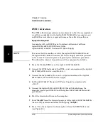
DVM Calibration
The DVM calibration procedure is semi-automatic in that it is accomplished
via software embedded in the Agilent 53147A/48A/49A. A computer and
an RS-232 serial cable are required to access the calibration software.
Equipment Required
A computer with an RS-232 serial interface and terminal software
Agilent 53150-60215 RS-232 Serial Cable
Agilent 6613C or 6614C Precision DC Power Supply
NOTE
To ensure that the results are valid, the Agilent 53147A/48A/49A and
the Agilent 6613C/6614C Precision DC Power Supply should be powered
on for at least 30 minutes prior to beginning the calibration procedure.
This allows the internal temperatures of the equipment to stabilize.
1
Press the
Display DVM
key on the Agilent 53147A/48A/49A.
2
Connect the DVM test leads to the DVM + and – connectors on the Agilent
53147A/48A/49A (red to + and black to –).
3
Connect the test prods to the + and – output connectors on the Agilent
6613C/6614C Precision DC Power Supply.
4
Set the 6613C/6614C Precision DC Power Supply to output exactly
+ 50.0 V.
5
Connect the Agilent 53150-60215 RS-232 Serial Cable between the
computer’s serial port (DB-25) and the Agilent 53147A/48A/49A’s serial
port (RJ-45).
6
Start the terminal software on the computer.
7
Send “
!acq 60
” from the terminal program to the Agilent 53147A/48A/49A
(be sure to type lowercase letters when typing “
!acq 60
”).
8
Press
“5”
on the computer to choose option 5 from the
DMM Tests
menu
(see Figure 2-8).
Summary of Contents for 53147A
Page 6: ...Contents vi Assembly Level Service Guide ...
Page 13: ...1 Performance Tests Verifying Specifications ...
Page 55: ...2 Service ...
Page 88: ...Chapter 2 Service Troubleshooting the Instrument 2 34 Assembly Level Service Guide 2 ...
Page 89: ...3 Replacing Assemblies Disassembly and Reassembly ...
Page 104: ...Chapter 3 Replacing Assemblies Removing the Power Supply 3 16 Assembly Level Service Guide 3 ...
Page 105: ...4 Replaceable Parts ...
Page 116: ...Chapter 4 Replaceable Parts Parts Identification 4 12 Assembly Level Service Guide 4 ...
Page 117: ...5 Backdating ...
Page 119: ...6 Specifications ...
Page 125: ...A Rack Mounting the Instrument ...
Page 134: ...Index Index 4 Assembly Level Service Guide Index ...


