Chapter 2 Service
Troubleshooting the Instrument
Assembly Level Service Guide
2-31
2
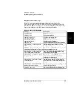
Self Test Error Messages
Table 2-4 lists and describes messages that are generated by the
instrument during Self-Test to indicate whether a component passed or
failed its test. These messages are sent via the RS-232 serial output only—
they do not appear on the instrument’s front-panel display.
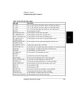
Table 2-4. Self-Test Messages
Message
Description
ROM TEST FAIL
ROM TEST OK
ROM failed read test.
ROM passed read test.
RAM DATA LINES OK
RAM DATA ERROR
RAM ADDR LINES OK
RAM ADDR ERROR
RAM TEST OK
RAM data lines passed test.
RAM data lines failed test.
RAM address lines passed test.
RAM address lines failed test.
RAM tests completed with no errors detected.
EEPROM FAIL - CONFIGURATION
DATA
The configuration data saved in EEPROM
memory is defective.
ROM FAIL; Computed checkbyte does
not match the value stored in EEPROM.
The checksum of the ROM data does not match
the value stored in EEPROM.
EEPROM FAIL - CONFIGURATION
DATA; Needs to be (re)initialized.
The EEPROM org code does not verify with
current revision of ROM code.
EEPROM FAIL - POWER CAL DATA;
Using default data
The checksum of the EEPROM power-
calibration table is bad. Factory default
calibration data will be used.
EEPROM FAIL - SAVED SETTINGS;
Using default data
The checksum of the user settings stored in
EEPROM is bad. Factory default settings will
be used.
EEPROM FAIL - SAVED SETTINGS;
Invalid EEPROM SAV n Data.
The checksum of one set of user settings (1 – 9)
stored in EEPROM is bad.
GPIB FAIL; Conf. Test
The GPIB hardware failed its confidence test.
Summary of Contents for 53147A
Page 6: ...Contents vi Assembly Level Service Guide ...
Page 13: ...1 Performance Tests Verifying Specifications ...
Page 55: ...2 Service ...
Page 88: ...Chapter 2 Service Troubleshooting the Instrument 2 34 Assembly Level Service Guide 2 ...
Page 89: ...3 Replacing Assemblies Disassembly and Reassembly ...
Page 104: ...Chapter 3 Replacing Assemblies Removing the Power Supply 3 16 Assembly Level Service Guide 3 ...
Page 105: ...4 Replaceable Parts ...
Page 116: ...Chapter 4 Replaceable Parts Parts Identification 4 12 Assembly Level Service Guide 4 ...
Page 117: ...5 Backdating ...
Page 119: ...6 Specifications ...
Page 125: ...A Rack Mounting the Instrument ...
Page 134: ...Index Index 4 Assembly Level Service Guide Index ...


