Chapter 3 Replacing Assemblies
Removing the Rear Panel Assembly
Assembly Level Service Guide
3-11
3
Removing the Rear Panel Assembly
Use the following procedure to remove the rear panel assembly:
1
Remove the shroud (see “Removing the Shroud” on page 3-7).
2
If the Battery Option is
not
installed, remove the four 4-40 self-locking hex
nuts that attach the battery opening cover to the rear panel (these nuts
are accessible from inside the chassis). Remove the battery opening cover,
and skip to step 5.
3
If the Battery Option
is
installed, remove the battery sled from the
Counter (for instructions on removing the battery sled, see Appendix C
of the
Agilent 53147A/148A/149A Operating Guide
).
4
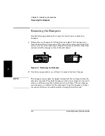
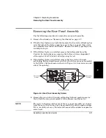
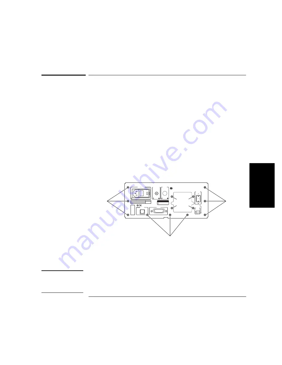
If the Battery Option is installed, remove the four 4-40 x 3/16-inch
self-locking flathead machine screws that attach the rear panel assembly
to the Battery Option chassis as shown in Figure 3-6 (two screws on each
side of the opening).
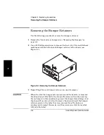
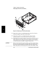
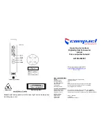
Figure 3-6. Rear Panel Assembly Screws
5
Remove the nine 4-40 x 3/16-inch self-locking flathead machine screws
that attach the rear panel assembly to the chassis (see Figure 3-6).
NOTE
The screw in the lower-left corner of the rear panel assembly (as viewed
from the rear of the Counter) may be covered by the serial-number sticker.
If it is, carefully cut away the lower-left corner of the sticker to expose the
screw head.
OPTIONS
001 Oven Time Base
002 Battery
Main Power
!
!
In or Out
Reference 10 MHz
Auxiliary
AC POWER
90-130 VAC 50/60/400 Hz
190-230 VAC 50/60 Hz
FUSE
1.5A T
250V
WARNING:
To avoid electrical shock:
Do not remove covers.
No user serviceable parts inside.
Refer all servicing to qualified personnel.
RS-
232
GPIB
Agilent
Counter/ Power Meter/ DVM
This unit must be earth grounded.
Made in U.S.A.
of domestic and foreign content
Battery
Battery
Charging
EXT DC
+
11 to 18 VDC
Rear panel
screws
Rear panel screws
Rear panel
screws
Battery
option
screws
Summary of Contents for 53147A
Page 6: ...Contents vi Assembly Level Service Guide ...
Page 13: ...1 Performance Tests Verifying Specifications ...
Page 55: ...2 Service ...
Page 88: ...Chapter 2 Service Troubleshooting the Instrument 2 34 Assembly Level Service Guide 2 ...
Page 89: ...3 Replacing Assemblies Disassembly and Reassembly ...
Page 104: ...Chapter 3 Replacing Assemblies Removing the Power Supply 3 16 Assembly Level Service Guide 3 ...
Page 105: ...4 Replaceable Parts ...
Page 116: ...Chapter 4 Replaceable Parts Parts Identification 4 12 Assembly Level Service Guide 4 ...
Page 117: ...5 Backdating ...
Page 119: ...6 Specifications ...
Page 125: ...A Rack Mounting the Instrument ...
Page 134: ...Index Index 4 Assembly Level Service Guide Index ...

