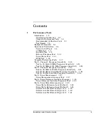
Chapter 1 Performance Tests
Equipment Required
1-4
Assembly Level Service Guide
1
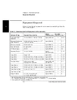
Equipment Required
Table 1-1 lists the test equipment and accessories needed to perform the
tests in this chapter.
Table 1-1. Recommended Test Equipment and Accessories
Instrument Type
Required Characteristics
Model
Recommended *
Quantity
Required
Use **
Synthesized Signal
Generator
10 Hz to 20 MHz, +7 dBm to –40 dBm
Agilent 3325A/B
2
OV, P, T
Microwave Synthesized
Signal Generator
10 MHz to 50 GHz, Accuracy >1 x 10
-10
+7 dBm to –50 dBm
Agilent 83650B
1
P, T
Microwave Amplifier
45 MHz to 50 GHz
Agilent 83051A
1
P, T
Digital Multimeter
6½ digit AC/DC
Agilent 34401A
1
OV, P
DC Power Supply
25 VDC
Agilent E3640A
1
OV
Frequency Counter
10 Hz to 125 MHz
Agilent
53150A/51A/52A
1
P, C, T
Power Meter
Range 1 mW
Agilent 432A
1
P, C, T
Power Meter
50 MHz to 50 GHz, +13 dBm to –50 dBm
Agilent 437B
1
P, C, T
Power Meter
100 kHz to 110 GHz, –70 dBm to +44 dBm
Agilent E4418B
1
P, C, T
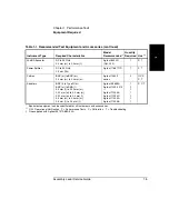
Thermistor Mount
SWR 1.05 at 50 MHz
Accuracy ±0.5% at 50 MHz
Agilent 478A-H75
or 478A-H76
1
P, T
Power Sensor
10 MHz to 18 GHz, -30 dBm to +20 dBm
Agilent 8481A
1
P, T
Power Sensor
50 MHz to 50 GHz, +13 dBm to –50 dBm
Agilent 8487A
1
P, C, T
Power Sensor Cable
2.4 mm to 2.4 mm, 5 ft.
Agilent 11730A
2
†
P, T
Power Sensor Cable
Agilent 8120-1082
1
P, T
Range Calibrator
3, 10, 30, 100, and 300 µW
1, 3, 10, 30, and 100 mW
Agilent 11683A
1
P
* Equivalent equipment can be substituted for all instruments and accessories.
** OV = Operational Verification
P = Performance Tests
C = Calibration
T = Troubleshooting
† One supplied with Agilent 53147A/48A/49A
Summary of Contents for 53147A
Page 6: ...Contents vi Assembly Level Service Guide ...
Page 13: ...1 Performance Tests Verifying Specifications ...
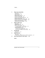
Page 55: ...2 Service ...
Page 88: ...Chapter 2 Service Troubleshooting the Instrument 2 34 Assembly Level Service Guide 2 ...
Page 89: ...3 Replacing Assemblies Disassembly and Reassembly ...
Page 104: ...Chapter 3 Replacing Assemblies Removing the Power Supply 3 16 Assembly Level Service Guide 3 ...
Page 105: ...4 Replaceable Parts ...
Page 116: ...Chapter 4 Replaceable Parts Parts Identification 4 12 Assembly Level Service Guide 4 ...
Page 117: ...5 Backdating ...
Page 119: ...6 Specifications ...
Page 125: ...A Rack Mounting the Instrument ...
Page 134: ...Index Index 4 Assembly Level Service Guide Index ...

