Chapter 1 Performance Tests
Test 2: Channel 2 Frequency Sensitivity
Assembly Level Service Guide
1-25
1
9
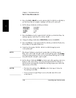
Repeat steps 6, through 8 for each of the remaining frequencies specified
for Test 2a. Don’t forget to change the power level when performing the
300 MHz and 19 GHz tests (53147A, 53148A, and 53149A) and the
16 GHz and 19 GHz tests (53149A only).
NOTE
It may be necessary to repeat Step 5.
10
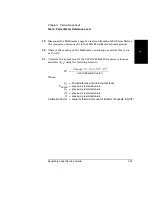
If all of the frequency values you recorded for Test 2a are correct, mark
Pass in the Performance Test Record. If any of the frequency readings you
recorded are incorrect, mark Fail in the Performance Test Record.
Test 2b: 22 GHz to 26.5 GHz Frequency Sensitivity
NOTE
This test is appropriate for the Agilent 53148A and 53149A.
1
Use the same test setup as described for Test 2a on page 1-23.
2
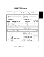
Set the output of the Agilent 83650B Synthesizer to the first frequency
specified for Test 2b in the Performance Test Record on page 1-40
(22 GHz).
3
Set the power output of the Synthesizer (read on the Power Meter) to a
power value 20 dBm above the value specified for Test 2b in the
Performance Test Record on page 1-40 (–5 dBm for the Agilent 53148A;
–7 dBm for the Agilent 53149A). (The added 20 dBm compensates for the
20 dB Attenuator.)
4
Record the frequency value read on the Counter (±1 count) for Test 2b in
the Performance Test Record on page 1-40.
5
Repeat steps 2, through 4 for each of the remaining frequencies specified
for Test 2b.
6
If all of the frequency values you recorded for Test 2b are correct, mark
Pass in the Performance Test Record for Test 2b. If any of the frequency
readings you recorded are incorrect, mark Fail in the Performance Test
Record.
Summary of Contents for 53147A
Page 6: ...Contents vi Assembly Level Service Guide ...
Page 13: ...1 Performance Tests Verifying Specifications ...
Page 55: ...2 Service ...
Page 88: ...Chapter 2 Service Troubleshooting the Instrument 2 34 Assembly Level Service Guide 2 ...
Page 89: ...3 Replacing Assemblies Disassembly and Reassembly ...
Page 104: ...Chapter 3 Replacing Assemblies Removing the Power Supply 3 16 Assembly Level Service Guide 3 ...
Page 105: ...4 Replaceable Parts ...
Page 116: ...Chapter 4 Replaceable Parts Parts Identification 4 12 Assembly Level Service Guide 4 ...
Page 117: ...5 Backdating ...
Page 119: ...6 Specifications ...
Page 125: ...A Rack Mounting the Instrument ...
Page 134: ...Index Index 4 Assembly Level Service Guide Index ...

