Chapter 2 Service
Calibration Procedures
Assembly Level Service Guide
2-7
2
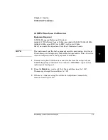
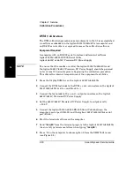
10 MHz Timebase Calibration
Equipment Required
10 MHz Frequency Reference Standard
Agilent 11730A Power Sensor Cable (provided with 53147A/148A/149A)
Agilent 10503 series BNC (m) to BNC (m) Coaxial Cable
Small, non-metallic adjustment tool for slotted screw heads
NOTE
The instrument and the test equipment must be powered on for at least
30 minutes prior to beginning this calibration procedure. This allows the
internal temperatures of the equipment to stabilize.
1
Connect an Agilent 10503 series coaxial cable from the output of your
10 MHz frequency standard to the Counter’s
CHANNEL 1
input on the
instrument’s front panel.
2
Press the
Resol
key, and verify that the resolution is set to
1 HZ
.
If necessary change the resolution to
1 HZ
.
3
If there is a label covering the calibration adjustment access hole,
remove it (see Figure 2-1).
Summary of Contents for 53147A
Page 6: ...Contents vi Assembly Level Service Guide ...
Page 13: ...1 Performance Tests Verifying Specifications ...
Page 55: ...2 Service ...
Page 88: ...Chapter 2 Service Troubleshooting the Instrument 2 34 Assembly Level Service Guide 2 ...
Page 89: ...3 Replacing Assemblies Disassembly and Reassembly ...
Page 104: ...Chapter 3 Replacing Assemblies Removing the Power Supply 3 16 Assembly Level Service Guide 3 ...
Page 105: ...4 Replaceable Parts ...
Page 116: ...Chapter 4 Replaceable Parts Parts Identification 4 12 Assembly Level Service Guide 4 ...
Page 117: ...5 Backdating ...
Page 119: ...6 Specifications ...
Page 125: ...A Rack Mounting the Instrument ...
Page 134: ...Index Index 4 Assembly Level Service Guide Index ...


