Chapter 2 Service
Calibration Procedures
2-8
Assembly Level Service Guide
2
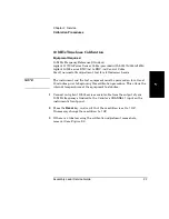
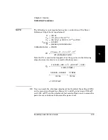
Figure 2-1. Calibrating the 10 MHz Frequency Reference Oscillator
4
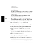
Insert a non-metallic, slot-type adjustment tool through the hole near the
bottom of the instrument’s left side and into the slot in the timebase
calibration screw.
5
Turn the calibration screw clockwise to increase the Counter’s reading or
counter-clockwise to decrease the reading until the frequency value
displayed on the Counter’s front panel is exactly
10,000,000 Hz
.
Calibration Access Hole
Summary of Contents for 53147A
Page 6: ...Contents vi Assembly Level Service Guide ...
Page 13: ...1 Performance Tests Verifying Specifications ...
Page 55: ...2 Service ...
Page 88: ...Chapter 2 Service Troubleshooting the Instrument 2 34 Assembly Level Service Guide 2 ...
Page 89: ...3 Replacing Assemblies Disassembly and Reassembly ...
Page 104: ...Chapter 3 Replacing Assemblies Removing the Power Supply 3 16 Assembly Level Service Guide 3 ...
Page 105: ...4 Replaceable Parts ...
Page 116: ...Chapter 4 Replaceable Parts Parts Identification 4 12 Assembly Level Service Guide 4 ...
Page 117: ...5 Backdating ...
Page 119: ...6 Specifications ...
Page 125: ...A Rack Mounting the Instrument ...
Page 134: ...Index Index 4 Assembly Level Service Guide Index ...


