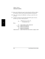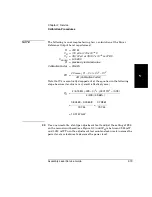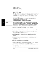
Chapter 2 Service
Calibration Procedures
Assembly Level Service Guide
2-21
2
Figure 2-8. DVM Tests Main Menu
9
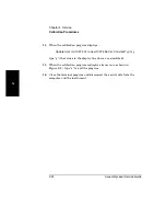
When the calibration program displays:
Apply 50.000 Volts Reference to the DVM. Ready? (y/n) y
type “
y
”.
10
When the calibration program displays:
Update from old 10974.12 to new 10974.1 Cal. Constant? (y/n) y
type “
y
” (the values in the display line above are simulated).
11
When the calibration program displays:
Apply –50.000 Volts Reference to the DVM. Ready? (y/n) y
12
Reverse the connection of the test prods in the + and – output connectors
on the Agilent 6613C/6614C Precision DC Power Supply (red to – output,
black to + output), or reverse the polarity of the power outputs.
13
Type “
y
”.
*********************** DVM TESTS ***********************
Select one of the following DVM tests:
1. Measure Fz - Frequency in Zero Mode
2. Measure Fr - Frequency in Positive Reference Mode
3. Measure Fn - Frequency in Negative Reference Mode
4. Measure Fm - Frequency in Input mode
5. Calculate and Save Calibration Constant.
6. Measure Voltage
7. Set the Gate time: 10ms - 1000 ms.
8. Choose Gated mode
9. Choose Reciprocal mode
A. Choose Single Measurement mode.
B. Choose Continuous Measurement mode.
E. Exit DVM tests.
Choose one of the above? (1 - 9, E) 5
Summary of Contents for 53147A
Page 6: ...Contents vi Assembly Level Service Guide ...
Page 13: ...1 Performance Tests Verifying Specifications ...
Page 55: ...2 Service ...
Page 88: ...Chapter 2 Service Troubleshooting the Instrument 2 34 Assembly Level Service Guide 2 ...
Page 89: ...3 Replacing Assemblies Disassembly and Reassembly ...
Page 104: ...Chapter 3 Replacing Assemblies Removing the Power Supply 3 16 Assembly Level Service Guide 3 ...
Page 105: ...4 Replaceable Parts ...
Page 116: ...Chapter 4 Replaceable Parts Parts Identification 4 12 Assembly Level Service Guide 4 ...
Page 117: ...5 Backdating ...
Page 119: ...6 Specifications ...
Page 125: ...A Rack Mounting the Instrument ...
Page 134: ...Index Index 4 Assembly Level Service Guide Index ...

