Chapter 2 Service
Troubleshooting the Instrument
Assembly Level Service Guide
2-33
2
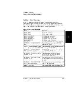
Table 2-6. RS-232 Error Messages
Message
Description
12V FAIL
The +12 VDC output from the power supply is not within specifications.
–12V FAIL
The –12 VDC output from the power supply is not within specifications.
–5V FAIL
The –5 VDC output from the power supply is not within specifications.
ADC FAIL
Failure detected in the ADC.
B1 SIGNAL PATH FAIL
Failure detected in the Channel 1 signal path.
B1 THRESHOLD FAIL
Failure detected in the Channel 1 threshold circuit.
B2 RF THRESHOLD FAIL
Failure detected in the Channel 2 RF threshold circuit.
B2 THROUGH-PATH
THRESHOLD FAIL
Failure detected in the Channel 2 through-path threshold circuit.
B2 HETERODYNE PATH
THRESHOLD FAIL
Failure detected in the Channel 2 heterodyne-path threshold circuit.
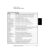
EEPROM FAIL - WRITE
Failure detected while writing to EEPROM.
FRONT PANEL FAIL
The front panel or its interconnecting cable are defective or not properly connected.
FPGA FAIL
Failure detected in the FPGA (Field Programmable Gate Array).
GPIB FAIL
Failure detected in the GPIB hardware.
HETERODYNE
PATH FAIL
Failure detected in the heterodyne-path circuit.
IIC FAIL
An attempt to write to the LCD display failed.
INSTCFG FAIL
The instrument’s configuration data is missing or corrupted.
OVER TEMPERATURE
The instrument’s internal temperature is above the limit.
PWR CAL FAIL
The instrument’s power-calibration data is missing or corrupted.
POWER METER FAIL
Failure detected in the Channel 2 power-measurement circuit.
RAM FAIL
Failure detected in RAM.
ROM FAIL
Failure detected in ROM.
SAV SET FAIL
One or more of the sets of user settings is missing corrupted.
SERVICE FAIL
The instrument’s service data is missing or corrupted.
THRU PATH FAIL
Failure detected in the through-path circuit of Channel 2.
VCO/COUNT CHAIN FAIL
Failure detected in the VCO or the Count Chain.
Summary of Contents for 53147A
Page 6: ...Contents vi Assembly Level Service Guide ...
Page 13: ...1 Performance Tests Verifying Specifications ...
Page 55: ...2 Service ...
Page 88: ...Chapter 2 Service Troubleshooting the Instrument 2 34 Assembly Level Service Guide 2 ...
Page 89: ...3 Replacing Assemblies Disassembly and Reassembly ...
Page 104: ...Chapter 3 Replacing Assemblies Removing the Power Supply 3 16 Assembly Level Service Guide 3 ...
Page 105: ...4 Replaceable Parts ...
Page 116: ...Chapter 4 Replaceable Parts Parts Identification 4 12 Assembly Level Service Guide 4 ...
Page 117: ...5 Backdating ...
Page 119: ...6 Specifications ...
Page 125: ...A Rack Mounting the Instrument ...
Page 134: ...Index Index 4 Assembly Level Service Guide Index ...

